Operation iTrans Fixed Point Single/Dual Gas Monitor
5-2 iTrans User Manual (P/N: 77023554-1)
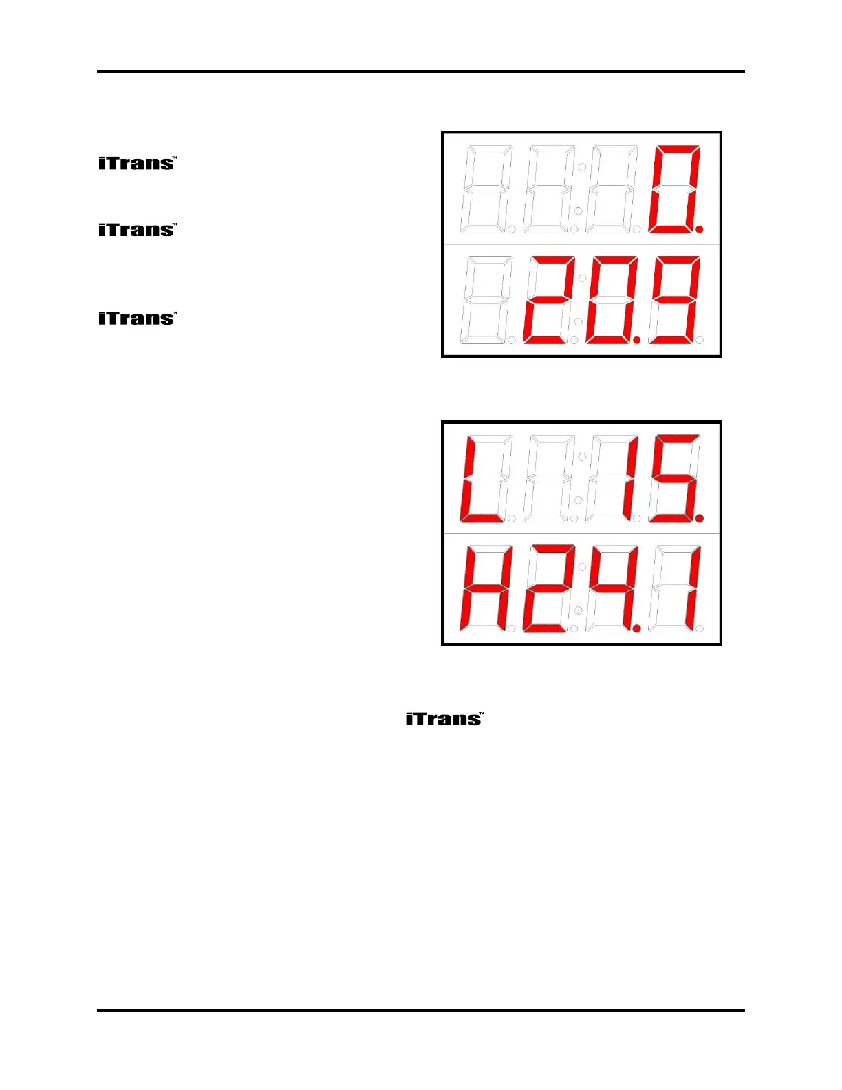
5.3. Normal Operating Mode
In Normal Operating Mode, the
gas monitor will display the
instantaneous readings for each sensor
wired into the unit. The top of the
display shows the gas
reading for Sensor 1. Sensor 1 should
have the internal dip switches set to 00
hex or 0F hex. The bottom row of the
display shows the gas
reading for Sensor 2. Sensor 2 should
have the internal dip switches set to F0
hex.
Figure 5-2. Sample Dual-Sensor
Display
As gas concentrations increase, the
respective channel’s readings will
respond accordingly. If low or high
alarm levels are exceeded, an alarm
indication will appear in the first digit
of the display. An “L” indicates a low
alarm while an “H” indicates a high
alarm. If a 4-20 mA fault occurs,
either a “P” indicating an open loop, or
an “U” indicating 4-20 over-range will
be present.
Figure 5-3. Sample Low and High
Alarm Displays
From the Normal Operating Mode, the can enter into the program mode
in one of two ways. To enter the Program Mode without opening the enclosure,
pass over the embedded reed switch located under CH1 with the magnetic wand
(see Figure 5-4). This will enter you into the non-intrusive program mode.
In this mode you can check sensor type, zero the unit, calibrate the unit, change the
span gas value, and view sensor span. With the enclosure top removed, Program
Mode can be entered using the “MODE” key. The available functions are listed in
Chapter 8: Troubleshooting.