System Wiring iTrans Fixed Point Single/Dual Gas Monitor
4-10 iTrans User Manual (P/N: 77023554-1)
4.6. Digital ModBus RTU Interface Wiring (J1)
4.6.1. ModBus Interface Wiring Overview
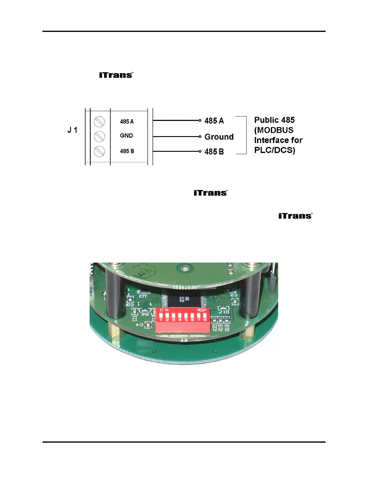
To interface the to a digital controller, PLC, or HMI, connect the power
and ground to the appropriate terminals mentioned above. The digital signals are
wired into the RS485A and RS485B terminals on the board. See Figure 4-9.
Figure 4-9. Wiring Diagram for the ModBus Interface
4.6.2. Setting the ModBus Address on the
Located on the back of the electronics module is an 8-position DIP switch.
This switch bank is used to set the ModBus Slave Address for the
unit. The address can be set from 1 to 255. Use the DIP switches to set the
binary representation of the desired address. 1 is bit zero, and 8 is bit 7. ON
represents a 1, and OFF represents zero. Refer to Appendix B for hex-to-
decimal equivalents.
Figure 4-10. Switch Bank for Setting ModBus Slave Address