11
SAL System
If the save destination is set to a network location, the INFO display may sometimes not show the number of
remaining image.
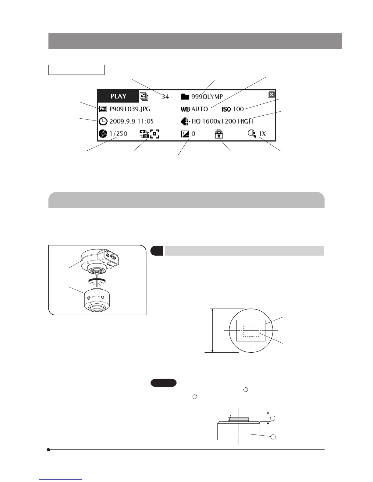
INFO display (PLAY)
2-4 Installation
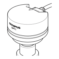
Fig. 1
This section pertains only to the installation of the DP21 microscope digital camera.
For the installation of the combined microscope, camera adapter, etc., refer to their instruction manuals and install care-
fully.
1
Installing the Camera Head
(Fig. 1)
Screw in the U-TV0.5XC-3 C-mount camera adapter @ into the mount
thread at the bottom of the camera head ². If you use a different C-
mount TV adapter, follow its instruction manual.
· As the photographed field is as shown below, use a camera adapter
having magnification of 0.5X to 1X. (If a 0.35X camera adapter is used, the
peripheral part of the image will be obscured.)
Field number
22
0.5X (FN 17.6)
1X (FN 8.8)
· If a C-mount TV adapter from other manufacturer than Olympus is used,
the optical performance of the system may not be manifested fully.
Be careful in using other manufacturer’s C-mount camera
adapter or C-mount lens
a
having a thread length over 4.5 mm
b . Otherwise, the threaded section will hit the inside of the
camera head and cause damage to it.
b
a
Recorded folder
name (p. 54)
White balance (p. 33)
ISO speed (p. 30)
Image quality
(p. 30)
Zoom (p. 27)Protect (p. 52)Exposure
adjustment (p. 26)
Metering area
(p. 26)
Exposure time
(p. 34)
Date / Time
(p. 53)
File name (p. 33)
1
2
Image No.
CAUTION