61
SAL System
POWER
+..
02
2-9-2 Connection
The following units are required for the connection of the microscope.
1. Control box (One of the following units is required.)
U-CBS/U-CBM/BX3-CBH
2. Revolving nosepiece (One of the following units is required.)
U-D7RES/U-D7REA
3. Hand switch for exposure
U-HSEXP
For how to connect the control box to the microscope, read the instruction manual for the control box in use.
· Remove the dust cover only from the areas used for the connections.
· Be sure to connect each connector to the module designated by Olympus. Olympus cannot guarantee any
of the system performance if a non-designated module is used.
· Be sure to set the POWER switch of the control box for coded units (U-CBS) to “
” (OFF in the high position)
before connecting cables.
· When connecting each connector, align the orientation of the male connector with the female connector
and insert all the way. If a connector has the lock screws, also tighten them firmly.
· Do not insert a male connector that does not match the female connector, as this may damage them.
CAUTION
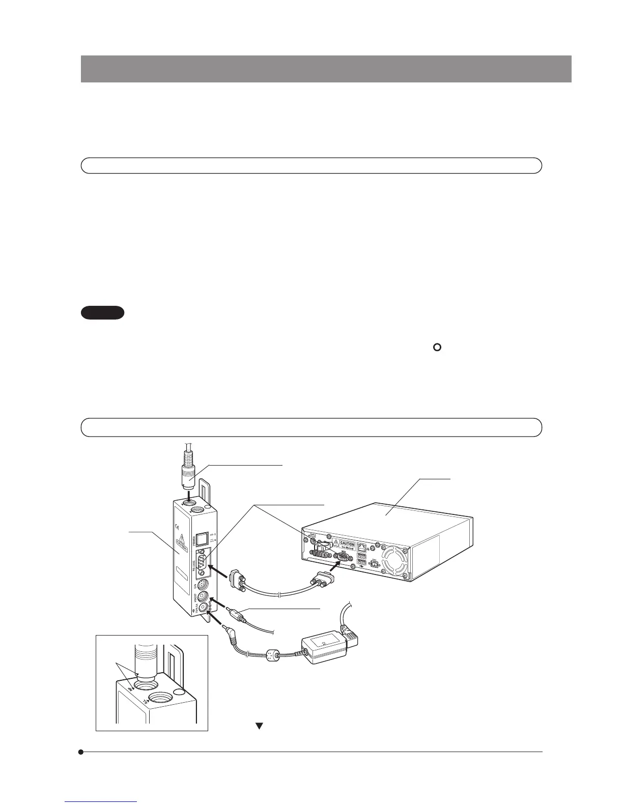
Connection of U-CBS
U-CBS
U-D7RES connector*
RS232C connectors
RS232C cable
(provided with
the U-CBS)
U-HSEXP connector
AC adapter for U-CBS
DP21-CB
*Connecting the U-D7RES connector
Align the
markings @ on the male and female connector and insert. (Fig. 1)
Fig. 1
1