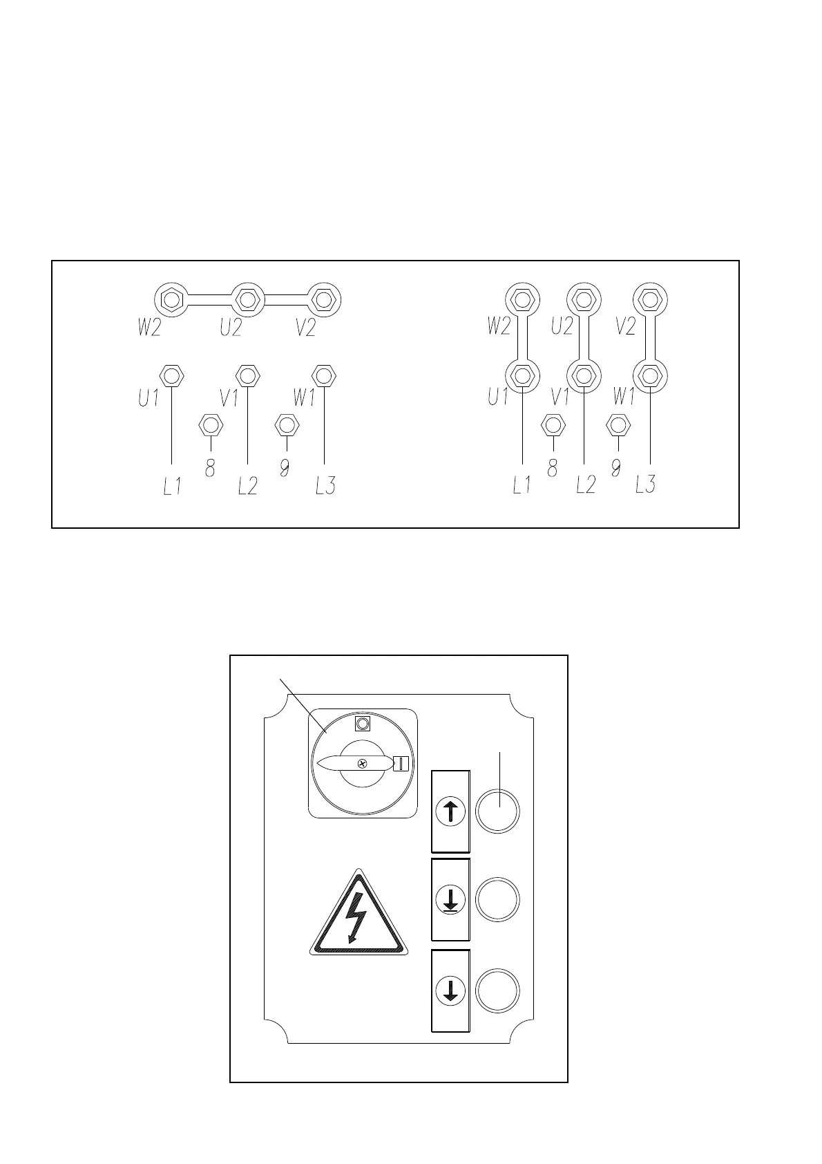
3)Eseguireicollegamentielettriciaimorsettidelmotore:
·
Aprirelascatolacontattipostasulmotoreedeffettuareicollega
-
menticomeindicatoinfig.48,asecondadellatensioneacuiver
-
ràalimentatoilponte.
·
Collegarelaprotezionetermica(Rif.8-9Fig.48).nelquadro
elettrico
I
ATTENZIONE
Ilquadroelettricovienepredispostodalcostruttoreperilfun
-
zionamentoa400Vtrifase,pertantosesidesiderafarfunzio
-
nareilpontea230Vtrifase,occorrecambiareilcollegamento
sultrasformatore(vederemorsettierasultrasformatorestes
-
so).
Fig.48 Collegamentimotoreetrasformatore
4)Chiudereilcoperchiodelquadroelettrico,ruotarel’interrutore
generale(QS,Fig.49)inposizione1,premereilpulsantedisalita
(rif.SB1,Fig.49)seilsensodirotazionenoncorrispondeconquello
dellafreccia,invertiretraloro2fasidell’alimentazione.
5)Controllareilcorrettofunziona
-
mentodeifinecorsadiestremitàco
-
lonnapremendolimanualmente.
Fig.49
3)Completetheelectricalconnectionstothemotorterminals:
·
Opentheboxofcontactslocatedonthemotorandconnect
themasshowninfig.48,accordingtothevoltageatwhichthe
rackwillbefed.
·
Connectedthetemperatureprotection(Ref.8-9Fig.48).
I
WARNING
Theelectricpanelsarearrangedbythemanufacturerforope
-
ratingat400V,three-phase:therefore,ifyouwishtheliftto
operateat230V,three-phase,changetheconnectiononthe
transformer(seeterminalboardofthetransformer).
Fig.48 Motorandtransformerconnections
4)Closethecoveroftheelectricbox,turnthemainswitch(QS,
Fig.49)toposition1,presstheuppushbutton(ref.SB1,Fig.49)
and,ifthedirectionofrotationdoesnotcorrespondtothatshown
bythearrow,reversethe2powersupplyphases.
5)Makesurethatthepostendli
-
mitswitchesworkproperlyby
pressingthemmanually.
26
QS
SB1
400V
230V