CAP.1. DESCRIZIONEDELLA
MACCHINA
Ilsollevatoreelettroidraulicoa2colonneèfisso,cioèancoratoal
suoloedèprogettatoecostruitoperilsollevamentoelostaziona
-
mentoinquotadiautoveicoliefurgoni.
Ilfunzionamentoèditipoelettroidraulico.
Ilsollevatoreècomposto,principalmenteda:
·
gruppostrutturafissa(basamento+colonne)
·
gruppimobili(carrello+bracci)
·
gruppidisollevamento;
·
quadrocomando
·
sicurezze.
Infigura4sonoindicatelevariepartichecompongonoilsollevato
-
reelezonedilavoroconsentiteeriservatealpersonaleaddetto,
attornoalsollevatorestesso.
Latocomando:èillatodelsollevatorechecomprendelazonari
-
servataall’operatoreincuisiaccedealquadrocomandi
Latoservizio:èillatooppostoaquellocomando.
Latoanteriore:èillatobracciolungo.
Latoposteriore:èillatobracciocorto.
Fig.4
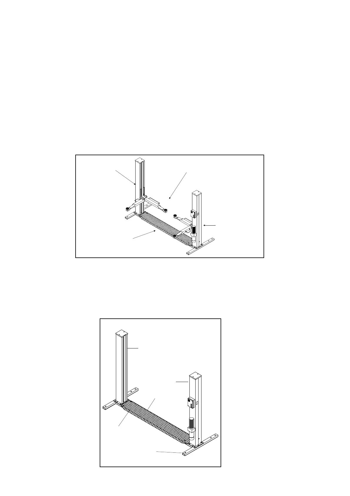
GRUPPOSTRUTTURAFISSA(Fig.5)
E’costituitoda:
·
UnBasamento(1)costruitoinprofilatidiacciaiosaldati,confori
perilfissaggioalsuolomediantetasselliadespansione(vedere
cap.4“Installazione“)edadiperilfissaggiotramitebullonatura
dellapiastradibasedellacolonna.
All’internodelbasamentoscorreuna
funediacciaio(2)chetrasmetteil
motodallacolonnamotore(3)alla
colonnaservizio(4).
Nellapartesuperioredelbasamento
èfissatalapedana(5)dicopertura
inlamierastriata.
·
2Colonneinlamieradiacciaio
piegataallacuibaseèsaldatauna
piastraforataperilfissaggioalba
-
samentomediantebullonatura.
Allacolonnacomandosonofissatiil
quadroelettricodicomandoelacen
-
tralinaidraulica.
All’internodiognicolonnasitrovano
igruppimobilidisollevamento
dell’automezzo.
Fig.5 Gruppistrutturafissa
CHAPTER1DESCRIPTIONOFTHE
MACHINE
The2-postelectro-hydrauliclift,isafixedinstallation.Thismeans
thatitisanchoredtothegroundanddesignedandbuiltforlifting
andpositioningautomobilesandvansatacertainheightoffthe
ground.
Theliftisdrivenbyanelectro-hydraulicoperatingsystem.
Theliftconsistsofthefollowingmainparts:
·
fixedstructure(base+posts);
·
mobileunits(carriage+arms);
·
liftunits;
·
controlbox;
·
safetydevices.
Figure4illustratesthevariouspartsoftheliftandtheworkareas
reservedforusebyoperatorsaroundthelift.
Commandside:thissideoftheliftincludestheareareservedfor
theoperatortoaccessthecontrolbox.
Serviceside:thisistheoppositesideofthecommandside.
Frontside:thesidewiththelongarm.
Rearside:thesidewiththeshortarm.
FIXEDSTRUCTURE(Fig.5)
Thisstructureconsistsof:
·
Abase(1)builtwithweldedsteelsections,withholestoconnect
ittothegroundusingexpansionbolts(seechapter4“Installa
-
tion)andnutsforboltingthepostbaseplate.
Asteelcable(2)runsinsidethebase
transmittingthemotionfromthemotorpost
(3)totheservicepost(4).Thechequered
plateplatformisattachedtothetopofthe
base.
·
2Postsbuiltwithbentsteelplate.The
baseisweldedtoadrilledplatetobebol
-
tedtothebase.
Theelectriccontrolboxandthehydraulic
powerunitareattachedtothecommand
post.
Thevehiclemobileliftingunitsarelocated
insideeachpost.
Fig.5Fixedstructureunits
6
Latocomando
Commandside
Latoservizio
Serviceside
Latoanteriore
Frontside
Latoposteriore
Rearside
1
2
4
3
5