MONTAGGIODEIBRACCI
1-Premendoilpulsantedisalita,portareicarrelliadun’altezzadi
circa70cm.daterra,quindipremereilpulsantedistazionamento,
PORTAREL’INTERRUTTOREGENERALE(QS)INPOSIZIONE
0ETOGLIEREL’ALIMENTAZIONEALSOLLEVATORE.
I
ATTENZIONE
Laspinadentata(10)elarondelladentata(5)devonoessere
accoppiatienonappoggiatiunosull’altro.Fareattenzionea
nondanneggiareidentidurantel’accoppiamento.Nonutiliz
-
zaremartellipereffettuarel’accoppiamento!
2-Ingrassareiforidelcarrello.
3-Inserireedavvitareleviticondadodifermodeibraccicomein
-
dicatoinfigura52,particolare“A”.
Fig.50
4-Montareibraccineisupportideicarrelliedinserirelespine
dentateneiforidelsupportocomeindicatoinfig.50.
Adoperazioneultimataoccorrecheilforodifissaggiodellespine
sulbracciosiaincorrispondenzadellasedericavatasullespine
stesse.Stringereigranibloccandoliconirelatividadi(fig.51).
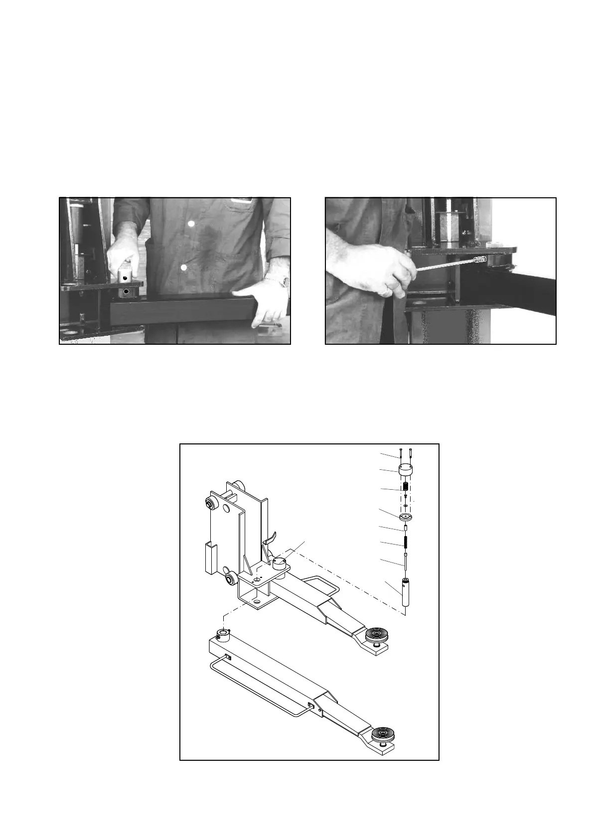
5-(Fig.52)Inserireilpernospin-
gimolla(1)nellaspinadentata
(10)esuccessivamentelamolla
(2),avendocuradiingrassarele
suddettepartiprimadimontarle.
6-Inserirelospinotto(3)nelforo
dellaspinadentata(10)esuc
-
cessivamenteposizionarelaron
-
delladentata(5)sull’estremità
scanalatadellaspina(10)che
sporgeràdalsupportodeibracci
(11)dialcunimillimetri.
Montarequindilamolla(8)facen
-
donecoincidereildiametrointer
-
noconlarondellapostasulla
rondelladentata(5).
Coprireconilcappellotto(7),in
-
serireleviti(9),centrandoifori
delsupportobracci,quindiavvi
-
tarle.
Fig.52
Montaggiodelbloccaggiobracci
ARMASSEMBLY
1-Presstheuppushbutton,raisethecarriagestoaheightofabo
-
ut70cmofftheground,thenpresstheparkpushbutton, SETTHE
MAINSWITCH(QS)TOPOSITION0ANDCUTOFFTHE
POWERSUPPLYTOTHELIFT.
I
WARNING
Thedowelpin(10)andlockingwasher(5)arematchedpairs
donotmixthemup.Beverycarefulnottodemagethespline
teethwhenfitting.Donotuseahammer!
2-Greasethecarriageholes.
3-Insertandtightenthescrewswiththelocknutofthearmsas
showninfig.52,detail“A”.
Fig.51
4-Mountthearmsintothecarriagesupportsandinsertthedowel
pinsintothesupportholesasshowninfig.50.
Aftercompletingtheoperation,theattachmentholeofthepinson
thearmmustcoincidewiththeseatonthosepins.Tightenthe
dowels,lockingthemwiththerelativenuts(fig.51).
5-(Fig.52)Insertthespring
thrustingpin(1)intothedowel
pin(1)andthenthespring(2),
makingsuretogreasetheafore
-
mentionedpartsbeforemoun
-
tingthem.
6-Insertthepin(3)intothehole
ofthedowelpin(10)andthen
positionthelockwasher(5)on
thegroovedendofthepin(10)
thatwillprojectfromthearm
support(11)byafewmillime
-
tres.
Thenmountthespring(8)ma
-
kingtheinternaldiametercoinci
-
dewiththewasherlocatedon
thelockwasher(5).
Coverwiththecap(7),insertthe
screws(9),centeringtheholes
ofthearmsupport,andthen
tightenthescrews.
Fig.52
Lockingarmsassembling
27
9
7
8
5
3
2
1
10
11