CAP.5FUNZIONAMENTOEDUSO
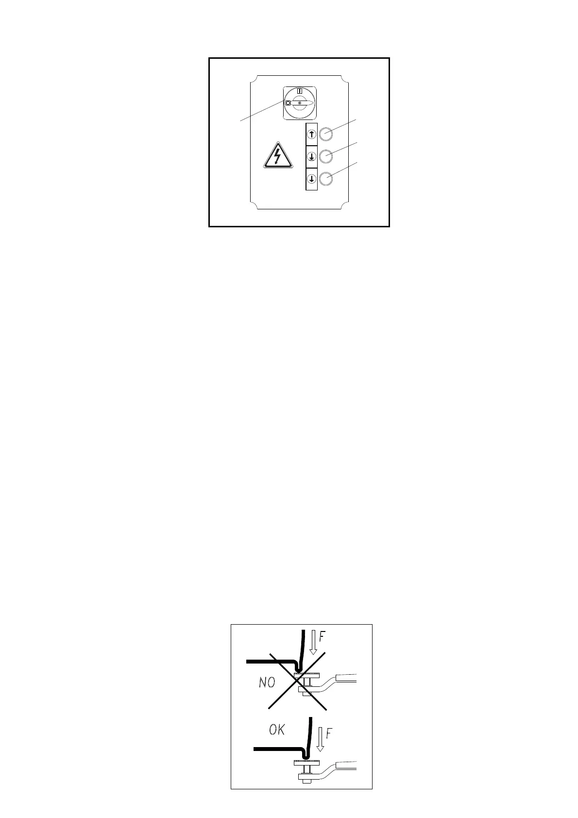
Icomandidelsollevatoresonoiseguenti:
INTERUTTOREGENERALE(QS)
POSIZIONE0:Ilsollevatorenonèinten
-
sione;èpossibilel’accessoall’internodel
quadroedèpossibilelucchettarel’interrut
-
toreperimpedirel’usodelsollevatore.
POSIZIONE1: dàtensionealsollevatoree
bloccalaportadelquadrocontroleapertu
-
reaccidentali.
PULSANTEDISALITA(SB1)
Tipo“uomopresente“,funzionasottoten
-
sionea24Ve,sepremuto,azionaimec
-
canismicheattuanoilsollevamentodel
carrello.
PULSANTEDIDISCESA(SB2)
Tipo“uomopresente“,funzionasottoten
-
sionea24Ve,sepremuto,azioneimec
-
canismicheattuanoladiscesadelcarrello.
PULSANTEDISTAZIONAMENTO
(SB3)
Tipo“uomopresente“,funzionasottotensionea24Ve,sepremu
-
to,azionel’elettrovalvoladiscaricoolionellacentralinaidraulica,
mettendoilcaricoinstazionamento.
SEQUENZADIFUNZIONAMENTO
Posizionareibraccidelsollevatoreneipuntidipresaprescrittidel
veicolo,regolandoipiattelliallastessaaltezza.
Ognivoltachesiscendeconicarrellifinoaterra,primadi
procedereadunanuovasalita,riverificarelaposizionedei
piattellisottoiltelaiodellavettura.
SOLLEVAMENTO
Posizionareibraccidelsollevatoreneipuntiprescrittidelveicolo
IATTENZIONE
Posizionareipiattellicorrettamentealfinediprevenirelaca-
dutadell’auto(Fig.61a)
Regolarel’altezzadeipiattelliinmodotalecheprendanoi4punti
disollevamentocontemporaneamente. Ruotarel’interruttoregene
-
raleinposizione1epremereilpulsantedisalitafinoalraggiungi
-
mentodiunaaltezzadicirca10cm.
Controllareancoraunavoltacheipiattellisianocorrettamentepo
-
sizionatisottolamacchinaedassicurarsicheibloccabraccisiano
correttamenteinseritispingendoibracciavantiedindietro.
Ruotarel’interruttoregenerale(QS)inposizione1epremereilpul
-
santedisalitafinoalraggiungimentodell’altezzadesiderata.
Teneresottocontrollosiailsollevatorecheilveicoloduranteilsol
-
levamento.Durantelacorsaimartellettisiinserisconoautomatica
-
menteinogniasoladelleastedisicurezza.
STAZIONAMENTO
Unavoltaraggiuntal’altezzadesideratapremereilpulsantedi
sta-zionamento(SB3).L’arrestodelmovimentoavvieneautomati
-
camen-teallorchéilmartellettosiappoggiasul
pianodellaprimaasolacheincontranodurante
ladiscesa.
DISCESA
Primadieffettuareladiscesaénecessariopro
-
cedereallosganciodeimartelletti;occorrepre
-
mereilpulsantedisalita(SB1)perottene-reun
sollevamentodicirca3cm.Premereilpulsante
didiscesa(SB2)chesganciaautomaticamentei
martellettiedazional’elettro-valvoladidiscesa.
Seduranteladiscesaicarrelliincontranoun’o
-
stacolocheimpedi-sceilproseguimentodella
corsasihal’interventodelmicrointerruttorefune
conconseguentearrestodelmovimento.
Fig.61a
CHAPTER5OPERATIONSANDUSE
Thelift,hasthefollowingcommands:
MAINSWITCH(QS)
POSITION0:Theliftisnotenergised.Itis
possibletoaccesstheinteriorofthebox
andlocktheswitchtopreventuseofthelift.
POSITION1:thisenergisestheliftandlock
thedooroftheboxtopreventitfrombeing
openedaccidentally.
UPPUSHBUTTON(SB1)
“Manpresent”type,itoperatesunder24V
and,ifpressed,activatesthemechanisms
thatliftthecarriage.
DOWNPUSHBUTTON(SB2)
“Manpresent”type,itoperatesunder24V
and,ifpressed,mechanismsthatbringthe
carriagedown.
PARKINGBUTTON(SB3)
“Manpresent”type,itoperatesunder24Vand,ifpressed,activa
-
testheoildischargeelectro-valveinthehydraulicpowerunit,
placingtheloadintheparkingposition.
OPERATINGSEQUENCE
Positiontheliftarmsintheholdpointsprescribedforthevehicle,
adjustingthediskstothesameheight.
Eachtimethecarriagesarebroughtdowntotheground,
checkthepositionofthedisksunderthechassisofthevehic
-
lebeforeraisingthecarriagesagain.
RAISING
Positiontheliftingarmsinthepointsofthevehicleindicated.
I WARNING
Positiontheplatescorrectlysoastopreventthecarfromfal-
ling(Fig.61a).
Adjusttheheightoftheplatessothattheygripthe4liftingpoints
simultaneously.Turnthemainswitchroundtoposition1andturn
theliftbuttonuntilaheightofabout10cmisreached.
Checkonceagainthattheplatesarepositionedcorrectlyunderthe
vehicleandmakecertainthatthearmlocksarefittedproperly,pu
-
shingthearmsforwardsandbackwards.
Turnthemainswitch(QS)toposition1andpresstheuppushbut
-
tonuntilreachingtherequiredheight.
Keeptheliftandthevehicleundercontrolduringlifting.
Asthecarriagesareraised,thesafetywedgesareinsertedauto
-
maticallyintoeachslotofthesafetyrods.
PARKING
Oncetherequiredheighthasbeenreached,presstheparking
pushbutton(SB3).Themovementisstoppedautomaticallywhen
thesafetywedgerestsonthelevelofthefirstslotthattheycome
incontactwithwhilethecarriagesarecomingdown.
LOWERING
Beforeloweringthecarriages,thesafetywed
-
gesmustbedisconnected.Presstheuppush
button(SB1)toliftthecarriageabout3cm.
Pressthedownpushbutton(SB2)thatautoma
-
ticallyreleasesthesafetywedgesandactivates
thedownelectro-valve.
Whenthecarriagesarelowered,iftheyruninto
anobstaclethatpreventsthemfrombeing
lowered,thistripsthecablemicroswitch,stop
-
pingthemovement.
31
QS
SB1
SB3
SB2
Fig.61