4-Agendosuldadodelcodulofune
delcarrellolatoopposto(fig.43),re
-
golarel’altezzadelcarrellostessoin
modocherisulti10mm.piùaltodel
carrellolatocomando(fig.58);que
-
stoalfinedicompensarel’allunga
-
mentodellafunesottocarico.Quindi
bloccareilcodulofunesulcarrello
latooppostoserrandol’apposito
controdado.
Fig.58 Regolazionedeicarrelli
5-Ilcostruttorefornisceilponteconimartellettidisicurezzapreta
-
rati.Verificarecomunqueconuncalibrocheladistanzafraimar
-
tellettidisicurezzaeleasteforatesiadi5mmcomeindicatoin
fig.59.Seladistanzanonrisultasseesseretale,agiresuidadidi
regolazione(AeB,fig.59)finoaportarlaalvalorerichiesto.
Fig.59 Regolazionedeimartelletti
6-Verificarecheallamassimaaltezzaladistanzatraimartelletti(1
Fig.59A)eleasole(2Fig.59A)dell’astadisicurezzasulle2co
-
lonnesia20mmminimodalsuoappoggio,unamisurainferirore
nondarebbeiltempoallasicurezzadiruotarerimanendoaggan
-
ciataall’asta.Senecessarioregolareilfinecorsasalita.
7-Montareicarteranterioridiprotezionecolonnafissandoliconle
vitiTEM8x16elerelativerondelle(fig.60).
8-Alimentareilponteeverificareilcorrettofunzionamentodelmi
-
crointerruttorefunepostonelbasamento.
9-Fissarelapedanadicoperturadelbasamentomedianteleviti
TSPEIM6x14.
Fig.59AMontaggiodeicarter Fig.59ACasingassembly
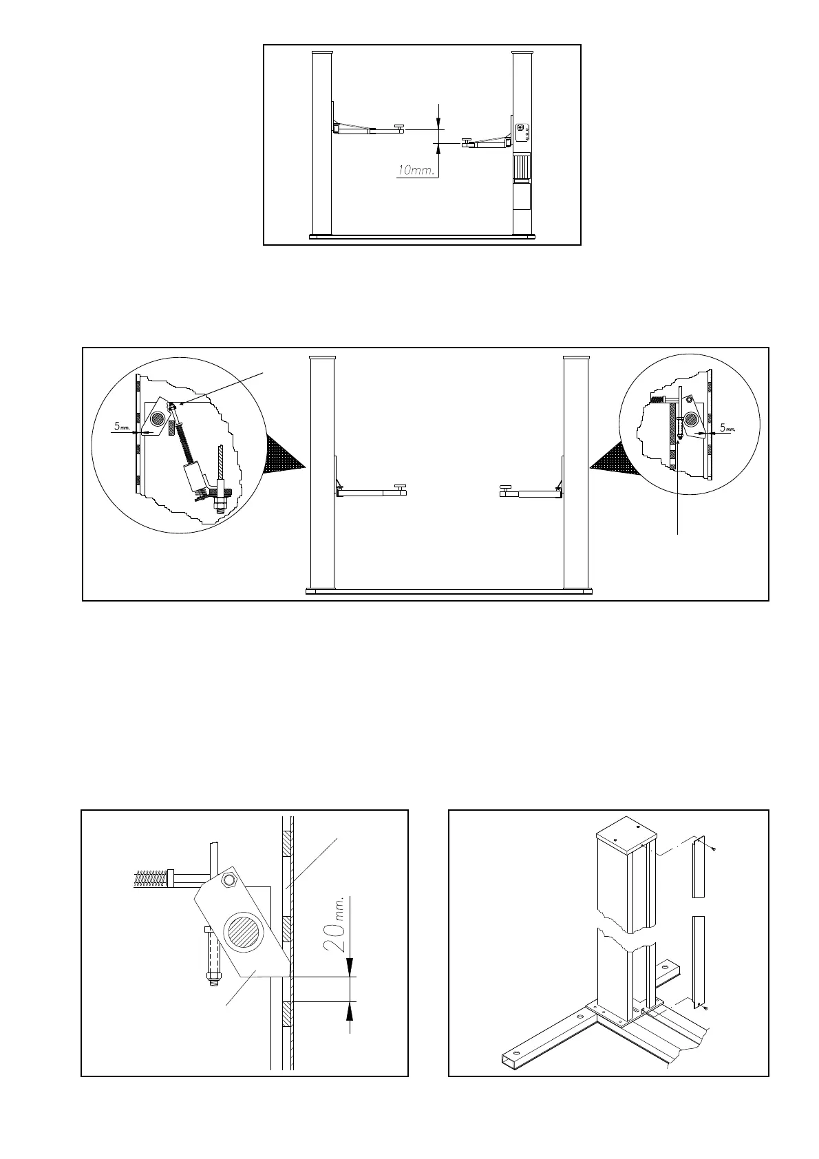
4-Usingthenutoftheoppositeside
carriagecableend(fig.43),adjustthe
heightofthecarriagesothatitis10
mmhigherthanthecarriageonthe
commandside(fig.58).Thiscompen
-
satesfortheelongationofthecable
underload.Thenlockthecableend
ontheoppositecarriagesidebytigh
-
teningthespecialcounternut.
Fig.58Carriageadjustment
5-Themanufacturersuppliestherackwiththesafetywedges
pre-calibrated.Inanycase,useagaugetocheckthatthedistance
betweenthesafetywedgesandthedrilledrodsis5mmasshown
infig.59.Ifthedistanceisnotcorrect,usetheadjustmentnuts(A
andB,fig.59)toobtaintherequiredvalue.
Fig.59 Safetywedgeadjustment
6-Checkthattothemaximumheightthedistancebetweenthe
wedges(1Fig.59A)andtheslots(2Fig.59A)ofthesafetystroke
onthe2columnsis20mmminimumfromsupport,aninferior
distancewouldnotgivethetimetothesafetywedgetorotate
keepinghookedtothestroke.Ifnecessaryregulatetheriselimit
switch.
7-Mountthefrontpostprotectioncasings,attachingthemwith
screwsTEM8x16andtherelativewashers(fig.60).
8-Feedtherackandverifythatthecablemicroswitchinstalledin
thebaseoperatescorrectly.
9-AttachthebasecoverplateusingscrewsTSPEIM6x14.
Fig.60Montaggiodeicarter Fig.60Casingassembly
29
A
B
1
2