7-Verificareilcorrettofunzionamentodeldispositivodibloccaggio
bracci,premendoversol’altoilpernospingimolla(1)eruotandoil
braccioinunodei2sensi,cosìchedopounabreverotazioneil
pernoritorninellasuaposizione(Fig.53).
Fig.53
8-Ripeterelestesseoperazioniperilmontaggiodeglialtri3brac
-
ci.
9-Montaresuibracciiparapiedidisicurezza(1e2,Fig.54),usan
-
dolevitiTEM10x10elerelativerondelle(3).
10-Regolarel’aperturadeibracciagendosulleviti(“A”,Fig.52)
cheandrannopoibloccateconirelatividadi.
I
ATTENZIONE
Controllareilcorrettofunzionamentodeibloccabracciintutte
leposizionipossibiliperilsollevamentodiunveicolo.
Fig.55
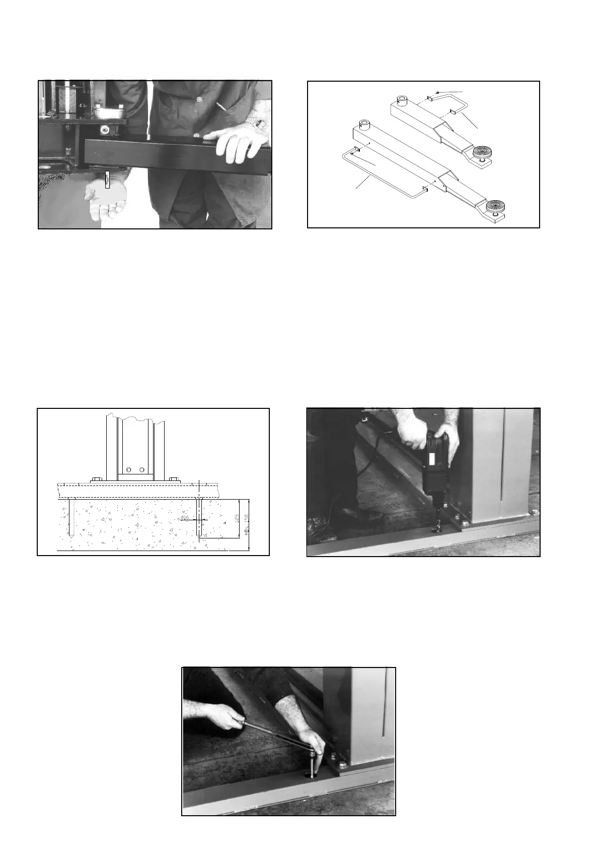
REGISTRAZIONEEBLOCCAGGIODELSOLLEVATORE
1-Forareilpavimentoconunapuntaelicoidaledacalcestruzzodi
diametro16mm(perFischerSLM10oø20perHiltiHBM12)per
unaprofonditàdi125mmusandocomedimadiforaturaiforinel
basamento(figg.55e56).
2-InserireitassellitipoFISCHERSLM10x65(oHILTIHBM12)
completamentenelpavimentoe,prima
delserraggio,verificarelaperpendicola
-
ritàinentrambigliassidellecolonne,
spessorandodovenecessarioconla
-
mierinididimensionedicirca80x80
mm.
3-Serrareconchiavedinamometricai
tassellidifissaggiodelbasamento,con
unacoppiadiserraggiodi70Nm
(Fig.57).
Fig.57
7-Makesurethatthearmlockingdeviceworkscorrectly,pressing
thespringthrustingpin(1)upwardsandturningthearminoneof
the2directions,sothatafterabriefrotationthepinreturnstoits
position(Fig.53).
Fig.54
8-Repeatthesameoperationsforassemblingtheother3arms.
9-Mountthefootguardsonthearms(1and2,Fig.54),usingthe
screwsTEM10x10andtherelativewashers(3).
10-Adjusttheopeningofthearmsbyusingthescrews(“A”,
Fig.52)whichwillthenbelockedwiththerelativenuts.
I
WARNING
Makesurethearmslockinallthepositionswheretheymight
liftavehicle.
Fig.56
LIFTADJUSTMENTANDLOCKING
1-Drillthefloorwithahelicalconcretebitwithadiameterof16
mm(forFischerSLM10orø20forHiltiHBM12)toadepthof125
mmusingtheholesinthebaseasadrillingtemplate(figures55
and56).
2-InsertFISCHERSLM10x65(orHILTIHBM12)anchorbolts
completelyintothefloorand,beforetig
-
htening,checktheperpendicularityin
bothaxesoftheposts,shimmingwhere
necessaryusingmetalstripswithadi
-
mensionofabout80x80mm.
3-Useatorquewrenchtotightenthe
anchorboltsinthebasetoatorqueset
-
tingof70Nm(Fig.57).
28
3
1
2
3