83
Calibrating the Bode 100
7.4 Calibration in the Impedance/Reflection Mode
By calibrating the Bode 100 you can remove the effects of the connection setup
on the accuracy of the measurement results in the Impedance/Reflection
mode. Without calibration the reference plane of the impedance measurements
is at the BNC connector of the Bode 100 source output. Therefore if a DUT is
connected through a cable, the measured impedance is the combination of the
cable's impedance and the DUT's impedance. By calibrating the Bode 100 you
can move the reference plane for the impedance measurement to the end of the
connection cable and fully remove the influence of the cable.
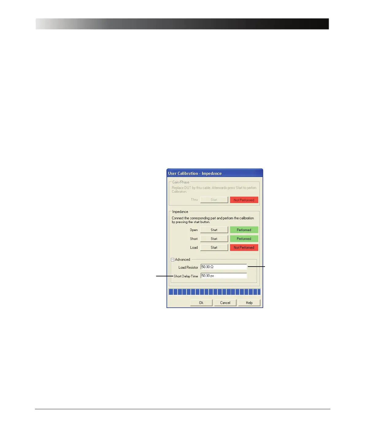
In the Impedance area of the calibration window, you can set the resistance of
the load resistor and the short delay time as shown below.
Hint: If the entered values of the load resistor and/or the short delay time differ
from the factory settings a yellow warning symbol appears after the Advanced
area has been collapsed.
Example: Measure the input impedance of the IF filter at the BNC connector of
the PCB (and not the impedance at the input of the cable connecting the filter).
Expected example duration: 20 minutes.
In this example you will learn step by step how to use the calibration of the
Bode 100 in the Impedance/Reflection mode.
Enter the exact
resistance of the load
used for calibration
Factory setting: 50
Ω
Enter the delay time of
the short circuit used for
calibration
Factory setting valid for
the short circuit delivered
with the Bode 100: 50 ps