11
Introduction
1.3 Connectors
Caution: To avoid damage of the Bode 100, check 12.3 "Absolute
Maximum Ratings" on page 136 for maximum input signals at the
CH 1 INPUT and CH 2 INPUT connectors and maximum reverse power at
the OUTPUT connector.
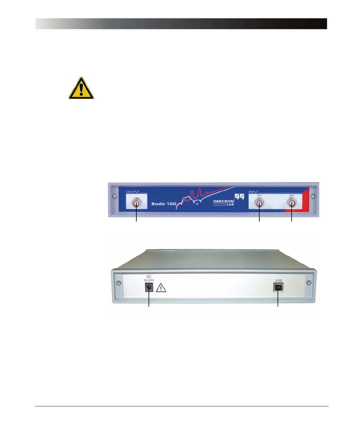
The Bode 100 provides the following connectors:
• OUTPUT (signal source output) on the front panel
• CH 1 INPUT (channel 1 input) on the front panel
• CH 2 INPUT (channel 2 input) on the front panel
• DC power input on the rear panel
• USB connector on the rear panel
Figure 1-2:
Bode 100 front view
Figure 1-3:
Bode 100 rear view
OUTPUT CH 1 INPUT
CH 2 INPUT
DC power input USB connector