21
Gain/Phase Mode
3.1.1 Internal Reference Connection
The basic formulas for the internal reference connection are summarized below.
Note: In the internal reference connection mode of the Bode 100, the reference
voltage for the gain/phase measurement is always .
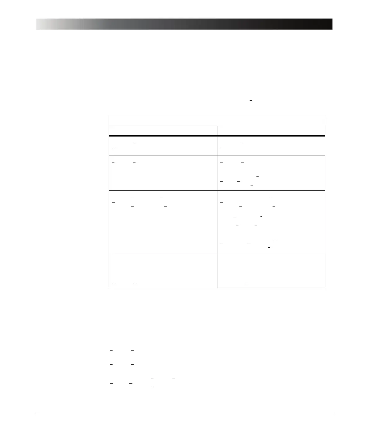
Table 3-1:
Formulas for Internal
Reference Connection
3.1.2 External Reference Connection
Independent of the selected input impedance at the channel 1and channel 2
inputs, the following formulas apply:
(Eq. 3-14)
(Eq. 3-15)
(Eq. 3-16)
V
0
2⁄
Channel 2 Input Resistance
50 Ω High Impedance
(Eq. 3-6) (Eq. 3-7)
(Eq. 3-8) (Eq. 3-9)
(Eq. 3-10)
= of the DUT (Eq. 3-11)
= (Eq. 3-12)
(Eq. 3-13)
If you make a through connection
from the source to CH 2:
0 dB gain will be displayed since
If you make a through connection
from the source to CH 2:
+6 dB gain will be displayed since
V
CH1
V
0
2
------
=
V
CH1
V
0
2
------
=
V
CH2
V
OUT
= V
CH2
V
OUT
=
V
IN
V
0
Z
IN
Z
IN
R
S
+()
--------------------------
•=
Hf()
V
CH2
V
CH1
-------------
2
V
OUT
V
0
-------------
•==
S
ji
f()
Hf()
V
CH2
V
CH1
-------------
2
V
OUT
V
0
-------------
•==
2
V
OUT
V
IN
-------------
•
Z
IN
Z
IN
R
S
+()
--------------------------
•
Hf() 2 H
T
f()
Z
IN
Z
IN
R
S
+()
--------------------------
••=
V
CH2
V
0
2⁄= V
CH2
V
0
=
V
CH1
V
IN
=
V
CH2
V
OUT
=
Hf() H
T
f()
V
CH2
V
CH1
-------------
V
OUT
V
IN
-------------
===