OMICRON 27
Application
1. Ensure that the Control device is switched off at the mains power switch.
2. Properly connect the Control device grounding terminal to substation ground.
3. Properly connect the CP TD12/15 measurement ground to ground of the asset to be measured.
4. Make sure that all cable connectors are clean and dry before connecting them tightly.
5. Connect the CP TD12/15’s "BOOSTER IN" to the Control device’s "EXT. BOOSTER" with the
booster cable.
6. Connect the CP TD12/15’s "SERIAL" to the Control device’s "SERIAL" with the serial cable.
7. Pull out the measuring cables from the cable drum and connect the test object to the CP TD12/15’s
measuring inputs IN A and IN B.
8. Connect the HV-cable from the test object to the CP TD12/15’s HV-output.
► Plug the HV-plug into the CP TD12/15 until the plug is securely fastened. Confirm this by trying to
gently pull it out.
► At the test object, insert the HV-cable’s plug carefully until you feel the plug "click" into place. Now
they are locked. Confirm this by trying to pull them out. This should not be possible now.
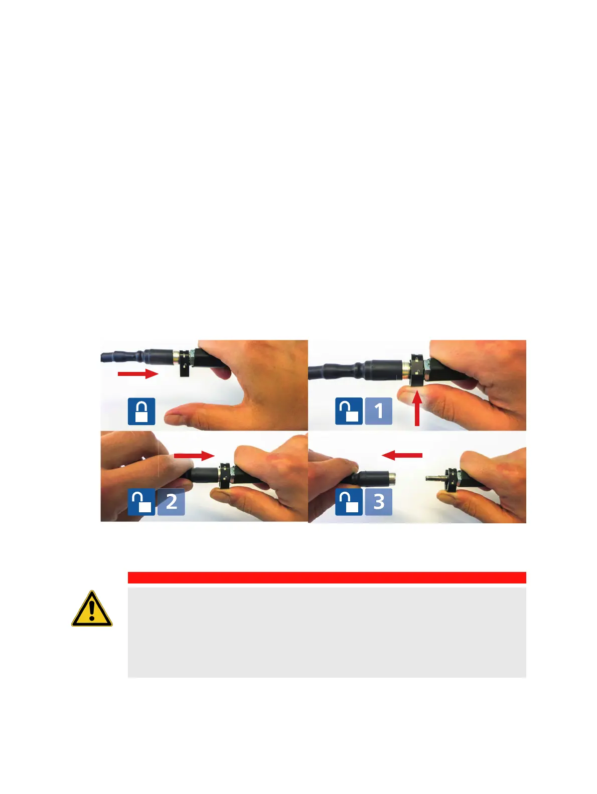
The images below show how to unlock the cable connection again. This is also shown on a label
fixed to the HV-cable.
► After the HV-cable connection is established, use the strain relief delivered with the HV-cable to
fasten it to the test object.
DANGER
Death or severe injury caused by high voltage or current
The HV-cable is double-shielded and therefore safe. However, the last 50 cm (20 inches)
of this cable has no shield.
► Avoid any direct contact of this part of the cable to ground potential or to any objects.
► Due to the life-hazardous high-voltage consider this part of the cable as live during
testing.

 Loading...


