OMICRON 41
Power transformers
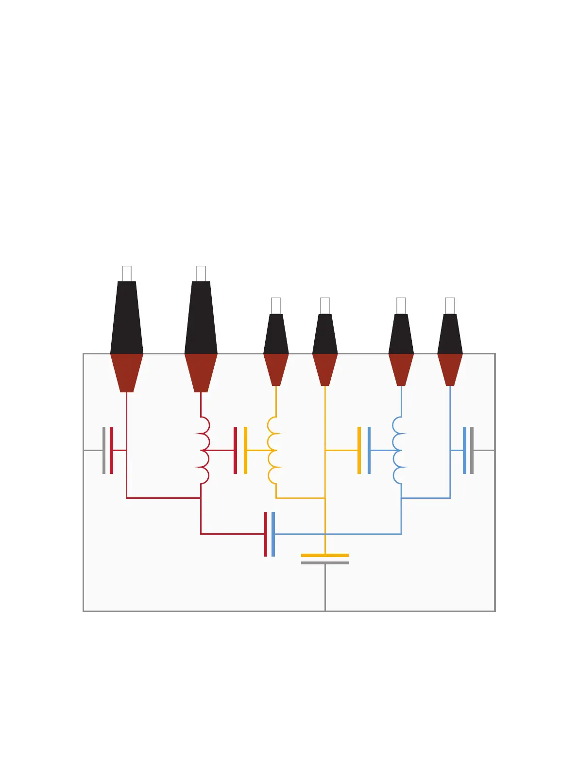
5.5 Three-winding transformer
In a three-winding transformer there are two parts of insulation which are formed by barriers and
spacers, C
HL
and C
LT
between the low- and tertiary-voltage windings (see Figure 5-8 below). Both
insulation parts are similar in construction to C
HL
in a two-winding transformer.
In addition to insulation C
H
, which is similar to C
H
in a two-winding transformer, there are the following:
insulation C
L
between the low-voltage winding and the tank, insulation C
T
between the tertiary winding
and the tank and insulation C
HT
between the high-voltage winding and the tertiary windings. C
T
is similar
to C
L
in a two-winding transformer, whereas C
L
in a three-winding transformer is mainly formed by the
insulation between the low-voltage winding and the tank and not the core limb. C
HT
is very small and
usually not of any specific importance as it is mainly formed by the stray capacitance from the HV-side
to the TV-side via the press construction above and below the windings.
Figure 5-8: Insulations of a three-winding transformer
All phases and the neutral terminal of one winding (H, L and T) have to be short-circuited. Due to the
inductance of the windings, resonant effects may occur and influence the measurement.

 Loading...


