CP TD12/15 User Manual
32 OMICRON
The dielectric losses in the insulation are caused by polarization and conduction phenomena. The
different polarization mechanisms are caused by various physical processes. Details can be found in
[1]
and
[2]
.
4.2 Measurement of Capacitance and Dissipation
Factor / Power Factor
Capacitance (C) and Dissipation Factor (DF) measurement was first published by Schering in 1919
3
and utilized for this purpose in 1924. The serial connected C
1
and R
1
represent the test object with
losses, C
2
the loss-free reference capacitor.
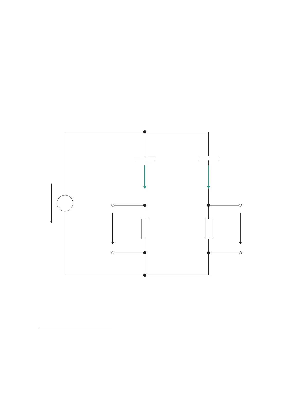
Figure 4-4: CP TD12/15 measuring principle
The CP TD12/15 test system utilizes a method similar to that of the Schering bridge. The main difference
is that the CP TD12/15 measuring principle does not require tuning for measuring C and DF. C
n
is a low
loss reference capacitor.
1. Zaengl, W.: Dielectric Spectroscopy in Time and Frequency Domain for HV Power Equipment, Part I: Theoretical
Considerations. IEEE Electrical Insulation Magazine, Vol. 19, No. 5, 2003, pp. 5-19
2. Krüger, M.: "Prüfung der dielektrischen Eigenschaften von Isolierflüssigkeiten", ÖZE, No. 5, Vienna, May 1986
3. Schering, H.: "Brücke für Verlustmessungen", Tätigkeitsbericht der Physikalisch-Technischen Reichsanstalt, Braunschweig
1919
U
0
(t)
U
N
(t) U
X
(t)Z
1
Z
2
I
CN
I
CX
Z
N
C
X
Z
X
, L
X
C
N
Reference path Measurement path

 Loading...


