CP TD12/15 User Manual
20 OMICRON
2.2.7 ePC Interface
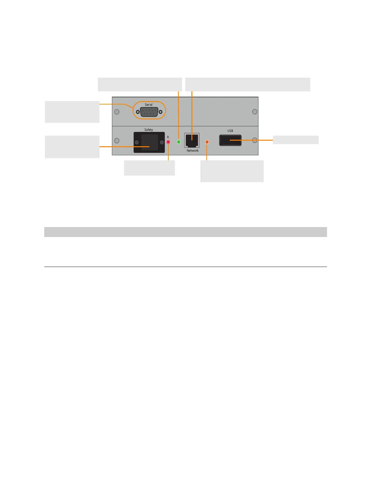
Figure 2-7: Connectors on the right side of the CPC 100 and the CPC 80
The following table describes the LEDs on the ePC interface:
Table 2-1: LEDs on the CPC 100 and CPC 80 ePC interface
LED Description
Green The CPC 100 or CPC 80 is properly connected to a PC or network.
Yellow Data are being transferred from/to the network.
Red For diagnosis purposes
USB connector
SAFETY connector
For OMICRON safety
accessories
RJ-45 socket
For connection to a PC or a network hub
Yellow LED
Data are being transferred
from/to the network.
Green LED
CPC connected to a PC or network
Red LED
For diagnosis
Serial interface
For connection to other
OMICRON devices

 Loading...


