OMICRON 23
Introduction
2.4 Functional components of the CP TD12/15
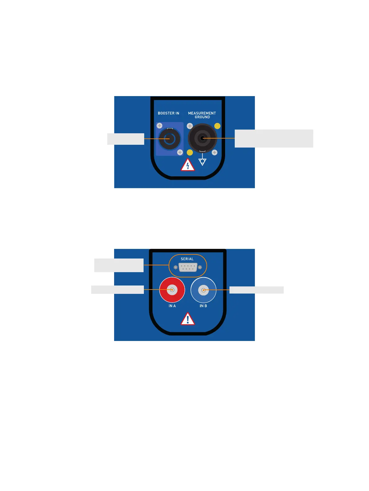
2.4.1 CP TD12/15 grounding terminal and Booster input
Figure 2-10: Grounding terminal and booster input of the CP TD12/15 (left side of the device)
2.4.2 CP TD12/15 serial interface connector and measuring inputs
Figure 2-11: Serial interface and measuring inputs of the CP TD12/15 (right side of the device)
* For more details on the interlock function, refer to 2.4.4 "Safety and interlock functions" on page 24.
Grounding terminal with interlock
function*
Booster input
IN B measuring input
IN A measuring input
Serial interface
connector

 Loading...


