CP TD12/15 User Manual
30 OMICRON
4 Introduction to capacitance and
dissipation factor measurement
Capacitance (C) and Dissipation Factor (DF) measurement is an established and important insulation
diagnosis method. It can detect:
• Insulation failures
• Aging of insulation
• Contamination of insulation liquids with particles
• Water in solid and liquid insulation
• Partial discharges
4.1 Theory
In an ideal capacitor without any dielectric losses, the insulation current is exactly 90° leading according
to the applied voltage. For a real insulation with dielectric losses this angle is less than 90°. The angle
δ
= 90° -
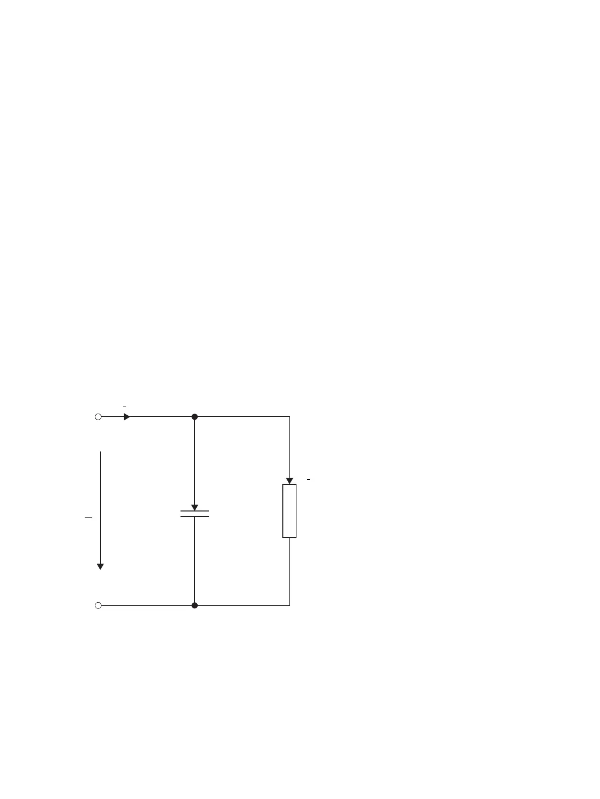
ϕ is called loss angle. In a simplified diagram of the insulation, C
p
represents the loss-free
capacitance and R
p
the losses (see Figure 4-1). Losses can also be represented by serial equivalent
circuit diagram with C
s
and R
s
. The definition of the dissipation factor and the vector diagram are shown
in Figure 4-2 on the following page.
Figure 4-1: Simplified circuit diagram of a capacitor

 Loading...


