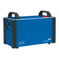
CP TD12/15 User Manual
10 OMICRON
1.5 Handling cables
Before handling the cables:
1. If a test is running, end the test.
2. Verify that the test has ended by checking the status lights of the Control device:
The green status light must be on and at the same time the red status light must off.
3. Lock the Control device to avoid any unauthorized execution of tests.
Note: For more details, refer to the corresponding User Manual of the Control device.
4. Ground and short-circuit the test object’s terminals using a suitable grounding set.
5. Disconnect the booster cable from the Control device.
6. Disconnect the booster cable from the CP TD12/15.
► The HV-cable must always be well attached and tightly connected to both the CP TD12/15 and the
test object. A loose connector or a connector falling off or into a test object carrying high-voltage is
life-hazardous. Make sure the connectors are clean and dry before connecting.
► Plug the HV-plug into the CP TD12/15 until the plug is securely fastened. Confirm this by trying to
gently pull it out.
► At the test object, insert the HV-cable’s plug carefully until you feel the plug "click" into place. Now it
is locked. Confirm this by trying to pull it out. This should not be possible now.
Do not connect any cable to the test object without a visible grounding of the test object.
► The HV-cable is double-shielded. However, the last 50 cm (20 inches) of this cable has no shield.
Therefore, consider this cable to be a live wire carrying life-hazardous high-voltage during testing!
► When the Control device is switched on this part of the cable has to be in the high-voltage area due
to an electric shock hazard!
► Never remove any cables from the CP TD12/15 or the test object during a test.
► Keep clear from zones in which high voltages may occur. Set up a safety barrier or establish similar
adequate means.
► Both low-voltage measuring cables must always be well attached and tightly connected to the
CP TD12/15’s measuring inputs IN A and IN B.
Make sure to insert the cables with the red and blue marker sleeves at the connector into the
correspondingly colored measuring inputs: IN A = red, IN B = blue.
► Use only original cables supplied by OMICRON.
WARNING
Death or severe injury caused by high voltage or current possible
The green status light indicates that the outputs of the Control device are not activated.
► Even if you switched off the Control device, wait until the red status light is off. As long
as this status light is on, there is still voltage potential on the output.

 Loading...