CP TD12/15 User Manual
42 OMICRON
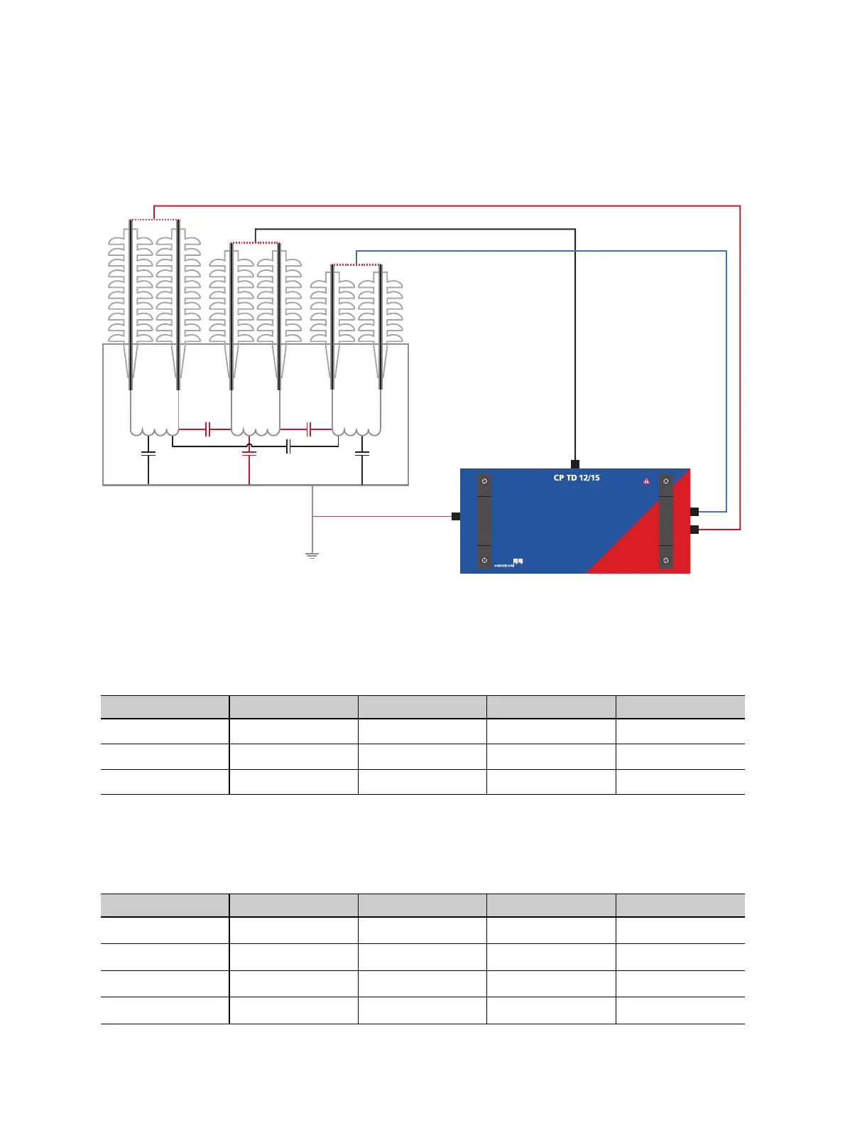
When the CP TD12/15’s HV-output is connected to the LV-winding and IN A and IN B to HV and tertiary,
the capacitances C
HL
, C
HT
and C
L
can be measured without reconnection (see Figure 5-9 and Tables
5-4 and 5-5 below).
Figure 5-9: CP TD12/15 connected to a three-winding transformer for the measurement of C
HL
, C
LT
and
C
L
With this setup the following 3 configurations are available:
Additionally, combinations of the different inputs are possible but as it is usually preferred to assess each
part of the insulation individually, they are less commonly used:
Table 5-4: Modes available with a measurement setup as seen in Figure 5-9
Mode IN A IN B Ground Result
UST-A Measured Guarded Guarded C
HL
UST-B Guarded Measured Guarded C
LT
GSTg-(A+B) Guarded Guarded Measured C
L
Table 5-5: Additional configurations available with a measurement setup as seen in Figure 5-9 if the
inputs are combined differently
Mode IN A IN B Ground Result
GSTg-(B) Measured Guarded Measured
C
L
+ C
HL
GSTg-(A) Guarded Measured Measured
C
L
+ C
LT
GST Measured Measured Measured
C
L
+ C
LT
+ C
HL
UST-(A+B) Measured Measured Guarded
C
HL
+ C
LT
LVHV
C
HL
C
L
C
H
C
LT
C
T
C
HT
TV
IN A
IN B
HV output
Measurement
ground

 Loading...


