2-6 Installation Instructions
Setup
External Return Bin Installation and Service Guide/67-2038 Rev D © 2011 Omnicell, Inc.
12. Cover the gray PowerCom cable with the black grommet taken off in step 9. Squeeze the
grommet together and push through the double D cutout on the left side.
Figure 2-14. Securing the grommet around the PowerCom cable
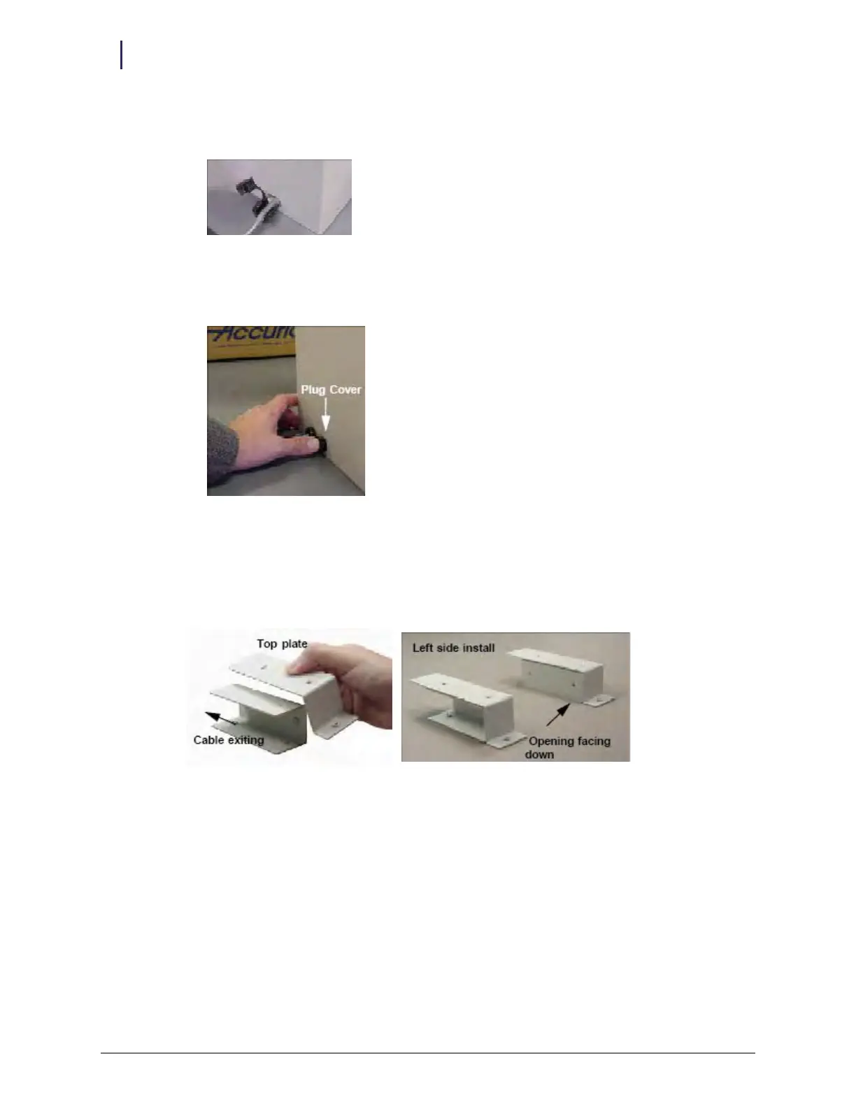
13. Snap the plug cover into the left-side D cutout adjacent to the cable assembly. The plug covers
the opening which will be used for future hardware developments.
Figure 2-15. Snapping in the plug
14. Rotate the lower plates. The open side of the left lower plate should face left. The open side of
the right lower plate should face down. This allows the left cover plate to protect the cables
being routed out of the ERB. The right cover plates will seal the cable openings on the right
side of the ERB.
Figure 2-16. Orientation for left cover plates