© 2011 Omnicell, Inc. External Return Bin Installation and Service Guide/67-2038 Rev D
Installation Instructions 2-7
Setup
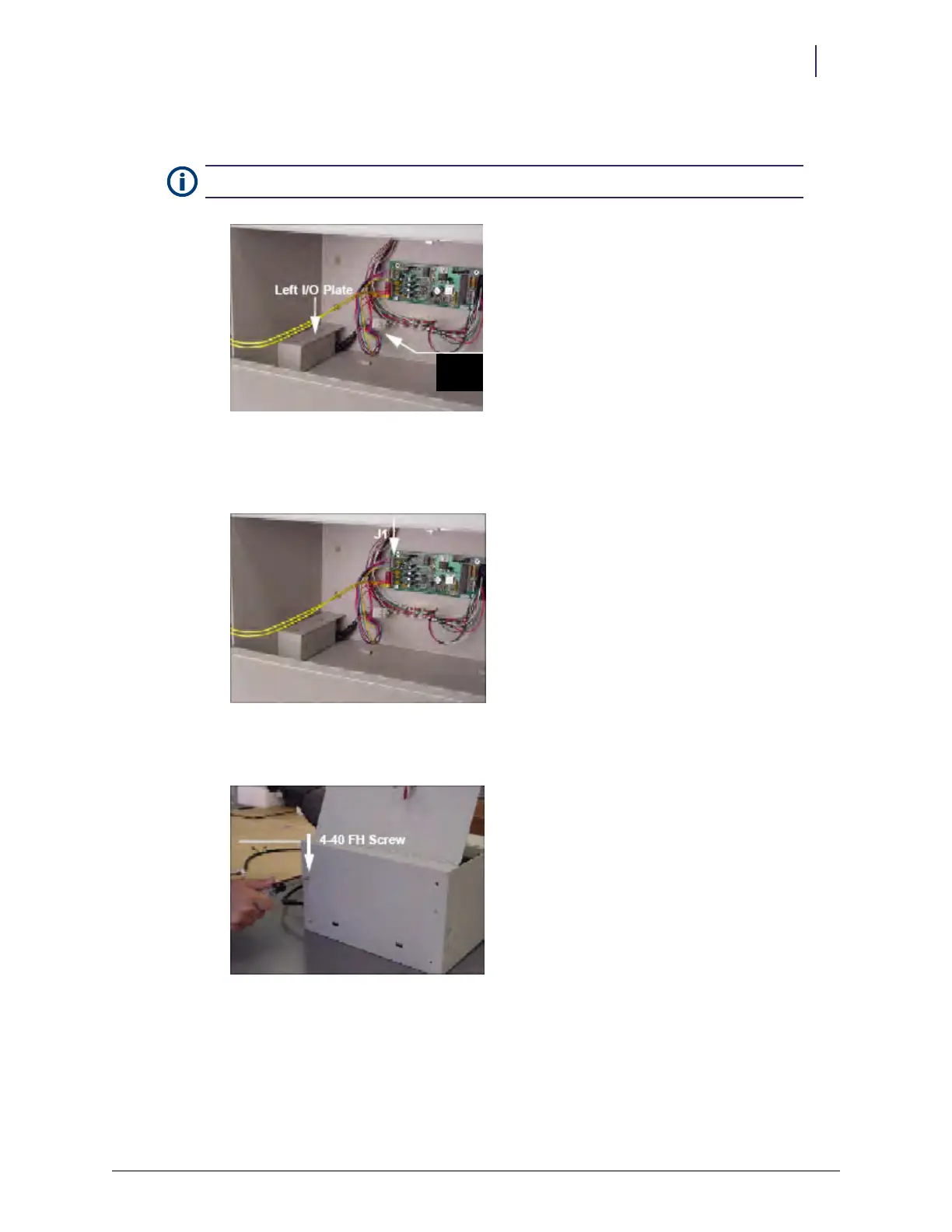
15. Install the left I/O cover plates. Take care not to pinch any wires.
Figure 2-17. Left I/O cover plate
16. Re-insert the PowerCom cable into J1 on the PC board. Make sure all 6 pins on the cable
connector are inserted.
Figure 2-18. J1 location
17. Secure the left I/O cover with the 4-40 flat head fastener removed in step 3 on page 2-2.
Figure 2-19. Replacing the fasteners
Note: The 6-pin white connector is not used.
6-pin
connector