© 2011 Omnicell, Inc. External Return Bin Installation and Service Guide/67-2038 Rev D
Installation Instructions 2-31
Installation on G3 Cabinets
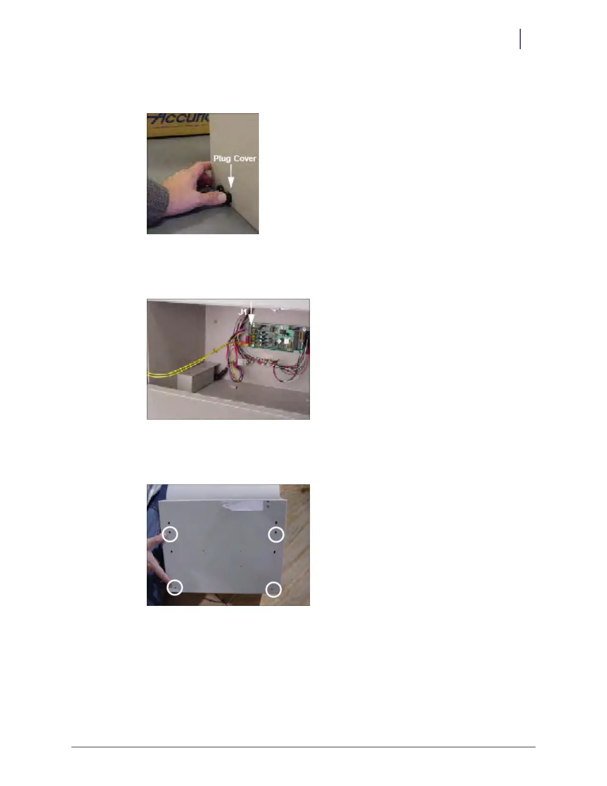
13. Snap the plug cover into the left-side D cutout adjacent to the cable assembly. The plug covers
the opening which will be used for future hardware developments.
Figure 2-82. Snapping in the plug
14. Re-insert the PowerCom cable into J1 on the PC board. Make sure all 6 pins on the cable
connector are inserted.
Figure 2-83. J1 location
15. Align the four circled drilled holes on the back of the ERB to the metal studs on the AWS
mounting bracket.
Figure 2-84. Aligning the drill holes