2-30 Installation Instructions
Installation on G3 Cabinets
External Return Bin Installation and Service Guide/67-2038 Rev D © 2011 Omnicell, Inc.
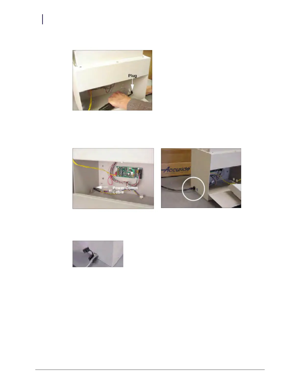
10. Remove the black plug cover by pushing against the groove from the inside with a screwdriver.
Figure 2-79. Removing the plug cover
11. Thread the PowerCom cable through the rear cutout on the opposite side of the ERB. The
correct orientation of the cable assembly exiting from the left side of the ERB is shown in the
figure below.
Figure 2-80. PowerCom cable routing
12. Cover the gray PowerCom cable with the black grommet taken off in step 9. Squeeze the
grommet together and push through the double D cutout on the left side.
Figure 2-81. Securing the grommet around the PowerCom cable