© 2011 Omnicell, Inc. External Return Bin Installation and Service Guide/67-2038 Rev D
Installation Instructions 2-35
Installation on G3 Cabinets
4. Remove the AUX cable connector at the rear of the electronic sled by pushing down on the
AUX connector and pushing it inside.
Figure 2-94. Removing the first AUX connector
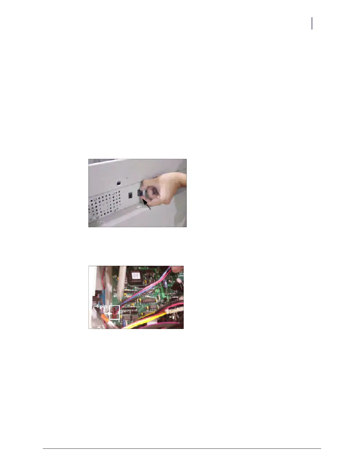
5. Remove the second AUX cable connector.
Figure 2-95. Removing the other AUX connector
6. Unplug the 4-pin connector from J24 (labeled AUX) on the PowerCom board, then remove
the cable.
Figure 2-96. 4-pin connector location