EasyManuals Logo

Omron 1S Series Startup Guide

Omron 1S Series
100 pages
To Next Page IconTo Next Page
To Previous Page IconTo Previous Page
Page #74 background imageLoading...
Page #74 background image
74
4.2. Adding the Safely-limited Speed (SLS) Function
This section describes how to add the SLS function to the project created in 3. Performing Setup.
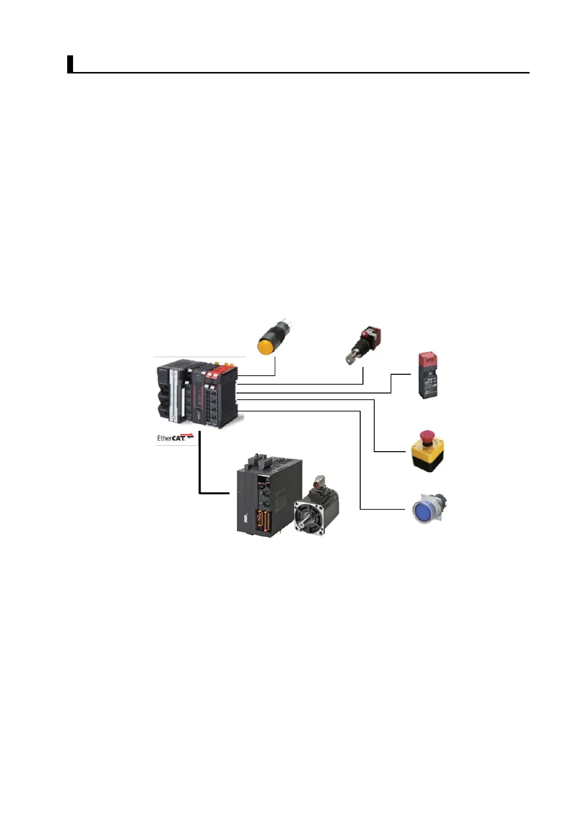
The operation of the servo system set up in this section is explained below.
1. When the error clear button is pressed, the errors of the standard controller and Servo Drive are
reset.
2. When the Safety Key Selector Switch is operated to switch to maintenance mode, the standard
controller changes the velocity command value to low speed. The Servo Drive activates the SLS
function to monitor present velocity.
3. When the guard with the Safety-door Switch is opened while the SLS function is inactive, the
motor torque is turned OFF.
4. When the Emergency Stop Pushbutton Switch is pressed, the motor torque is turned OFF.
5. When the safety reset button is pressed, the errors of the Safety-door Switch and Emergency
Stop Pushbutton Switch are reset.
1. Error clear button
3. Safety-door Switch
4. Emergency Stop
Pushbutton Switch
5. Safety reset button
2. Safety Key Selector Switch

Table of Contents

Other manuals for Omron 1S Series

Questions and Answers:

Question and Answer IconNeed help?

Do you have a question about the Omron 1S Series and is the answer not in the manual?

Omron 1S Series Specifications

General IconGeneral
Safety FunctionSTO (Safe Torque Off)
Motor Capacity50 W to 15 kW
Output Power50 W to 15 kW
Communication InterfaceEtherCAT, MECHATROLINK-II/III
FeedbackIncremental Encoder
Operating Temperature0 to +55°C
Protection FeaturesOvercurrent, Overvoltage
Ambient Humidity20% to 90% RH (non-condensing)
InstallationPanel Mount
WeightVaries by model
Storage Temperature-20 to 85°C

Related product manuals