Display Status Checks
Name Display status
PWR (Power LED) ON
FS (FS LED) OFF
RUN (RUN LED) OFF
PRG (Program LED) OFF
ERR (Error LED) OFF
EtherCAT L/A IN ON
EtherCAT L/A OUT OFF
EtherCAT RUN ON
EtherCAT ERR OFF
When the display status is other than shown above, refer to 3-1-2 Name of Each Status Indicator
on
page 3-2 and Section 9 Troubleshooting on page 9-1 for countermeasures.
Seven-segment LED Indicator
The figure below shows the seven-segment LED indicator on the data display.
When the power is turned ON, the node address value set by the ID switch is displayed, and then the
display changes according to the value set at 7SEG Monitor Item Selection (3052Hex-52Hex).
When an alarm occurs, the alarm code is displayed, and when a light alarm occurs, the light alarm
code is displayed.
Parameter No. Function name Data Default data Unit
3052Hex-52Hex
7SEG monitor (Item selec-
tion)
100 to 400
0: Display drive status
1: ID by rotary switch
-
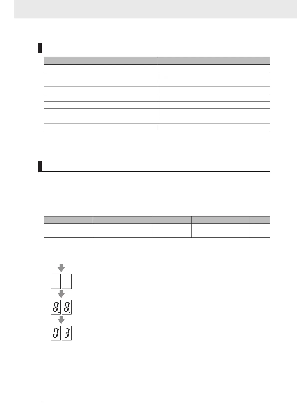
Transition of seven-segment LED indicator during power ON
All out
All lit
Node address display
Display example: MSB (x16) = 0, LSB (x1) = 3
Power-on
5 Operation and Test Run
5-8
M1 Series EtherCAT Type User’s Manual (I670)
 Loading...


