OFFON
OFFON
OFFO
N
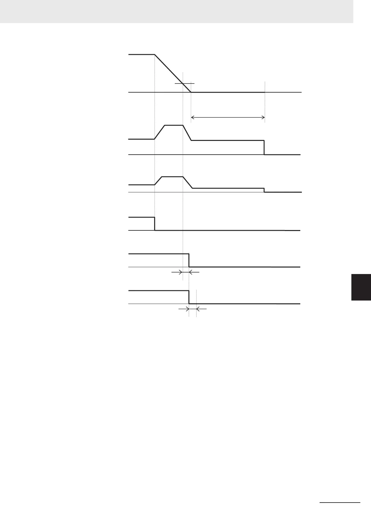
300EHex-48H:
Brake Control Brake-applied Frequency
3004Hex-1AHex = 0:
1st Stop Frequency
Output frequency
Output current
RUN command
Brake release signal
“BRK”
300EHex-49Hex: Brake Control Brake-applied Timer
Brake confirmation signal
“BOK”
3020Hex-51Hex: Brake Error Detection Time
Vector control Operation time chart at stop
3004Hex-28Hex:
1st Stop Frequency Holding Time
Torque command
Note
The above sequence chart shows an example where one of Input Terminal [DI1] to [DI7] Function Selection
(3005Hex-02Hex to 3005Hex-06Hex, 3005Hex-63Hex, 3005Hex-64Hex) is set to “65: BOK (brake confirma-
tion signal).”
At acceleration
1. When the RUN command is input, the inverter starts output.
2. When both the output current and output frequency (in V/f control) and the output current and
torque command (in vector control) reach the brake signal release level (300EHex-45Hex,
300EHex-46Hex, 300EHex-60Hex), the inverter waits for the time set at Brake Control Brake-
release Timer (300EHex-47Hex) and then outputs the brake release signal (3005Hex-15Hex,
3005Hex-1CHex = 57: BRK).
3.
After the brake release signal is output, the inverter waits for input of the brake confirmation sig-
nal (3005Hex-02Hex to 3005Hex-06Hex, 3005Hex-63Hex, 3005Hex-64Hex = 65: BOK) for the
time set at Brake Error Detection Time (3020Hex-51Hex).
7 Vector Control and Applied Functions
7-75
M1 Series EtherCAT Type User’s Manual (I670)
7-9 Brake control function
7
7-9-1 Operation Sequence of Brake Control Function
 Loading...


