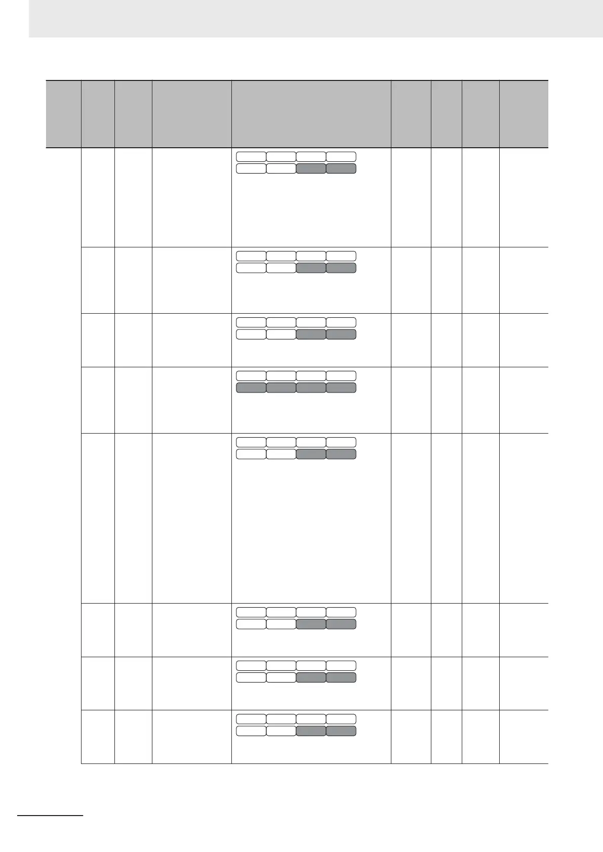
Index
(hex)
Sub-
index
(hex)
Pa-
rame-
ter No.
Function name Monitor or data range
Default
data
Set-
ting
dur-
ing
RUN
Unit
PDO
map
0B A10 2nd DC Injection
Braking Level
V/f DTV
PG V/f PG DTV
SLV PGV
PM SLV PM PGV
0 to 100 (HHD mode)
0 to 80 (HND/HD mode)
0 to 60 (ND mode)
Based on inverter rated current
0
√
% Possible
0C A11 2nd DC Injection
Braking Time
V/f DTV
PG V/f PG DTV
SLV PGV
PM SLV PM PGV
0.00: Disable
0.01 to 30.00
0.00
√
s Possible
0D A12 2nd Starting Fre-
quency
V/f DTV
PG V/f PG DTV
SLV PGV
PM SLV PM PGV
0.0 to 60.0
0.5
√
Hz Possible
0E A13 2nd V/f Charac-
teristics Selection
V/f DTV
PG V/f PG DTV
SLV PGV
PM SLV PM PGV
0: Variable torque load
1: Constant torque load
1 --- --- Possible
0F A14 2nd Drive Control
Selection
V/f DTV
PG V/f PG DTV
SLV PGV
PM SLV PM PGV
0: IM V/f control
1: IM Dynamic torque vector control
without speed sensor
3: IM V/f control with speed sensor
4: IM Dynamic torque vector control
with speed sensor
5: IM Vector control without speed
sensor
6: IM V
ector control with speed sen-
sor
0 --- --- Possible
10 A15 2nd Motor Pole
Number
V/f DTV
PG V/f PG DTV
SLV PGV
PM SLV PM PGV
2 to 128
4 --- Poles Possible
11 A16 2nd Motor Ca-
pacity
V/f DTV
PG V/f PG DTV
SLV PGV
PM SLV PM PGV
0.01 to 1,000
5.50 --- kW Possible
12 A17 2nd Motor Rated
Current
V/f DTV
PG V/f PG DTV
SLV PGV
PM SLV PM PGV
0.00 to 500.0
21 --- A Possible
Appendices
A-148
M1 Series EtherCAT Type User’s Manual (I670)