RST: Alarm reset
FWD: Forward command
REV: Reverse command
(All bits are ON with 1 regardless of the positive/negative logic setting.)
Example:
Operation command (3002-07 hex) = FWD, DI1 = ON
0000 0000 0000 0101
b
= 0005 hex →
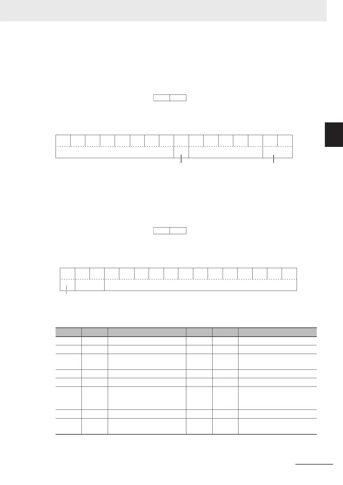
Data Format [15]: General-purpose Output Terminal
15 14 13 12 11 10 9 8 7 6 5 4 3 2 1 0
0
0 0
Not used
General-purpose output
0 0 RO
DO2 DO1
0 0 0 0 0 0 0 0
General-purpose output
Not used
RO: Relay output
FWD: Forward command
REV: Reverse command
(All bits are ON with 1 regardless of the positive/negative logic setting.)
Example:
Output Terminal Monitor (3003-10 hex) DO1 = ON
0000 0000 0000 0001
b
= 0001 hex →
Data Format [16]: Operation Status
Operation status
1
5 14 13 12 11 10 9 8 7 6 5 4 3 2 1 0
00
Not used Operation status
BUSY
ALMRL TL NUV BRK INT EXT REV FWDDEC
ACC
IL VL
(All bits are ON or active with 1.)
Bit Symbol Description Bit Symbol Description
0 FWD During forward operation 8 IL During current limiting
1 REV During reverse operation 9 ACC During acceleration
2 EXT Direct DC braking
(or during pre-exciting)
10 DEC During deceleration
3 INT Inverter shut down 11 ALM Alarm relay
4 BRK During braking 12 RL Communications effective
5 NUV Main circuit DC voltage estab-
lished
(Undervoltage with 0)
13 0 ---
6 TL Torque limiting 14 0 ---
7 VL During voltage limiting 15 BUSY During parameter code data
writing
Example: Operation Status 1 Monitor (3003-0F hex) = During forward operation and during acceler-
ation
Appendices
A-177
M1 Series EtherCAT Type User’s Manual (I670)
A-4 Lists of Manufacturer Specific Objects 2
(Inverter Parameters)
A
A-4-17 Communication Data Formats of Parameters
 Loading...


