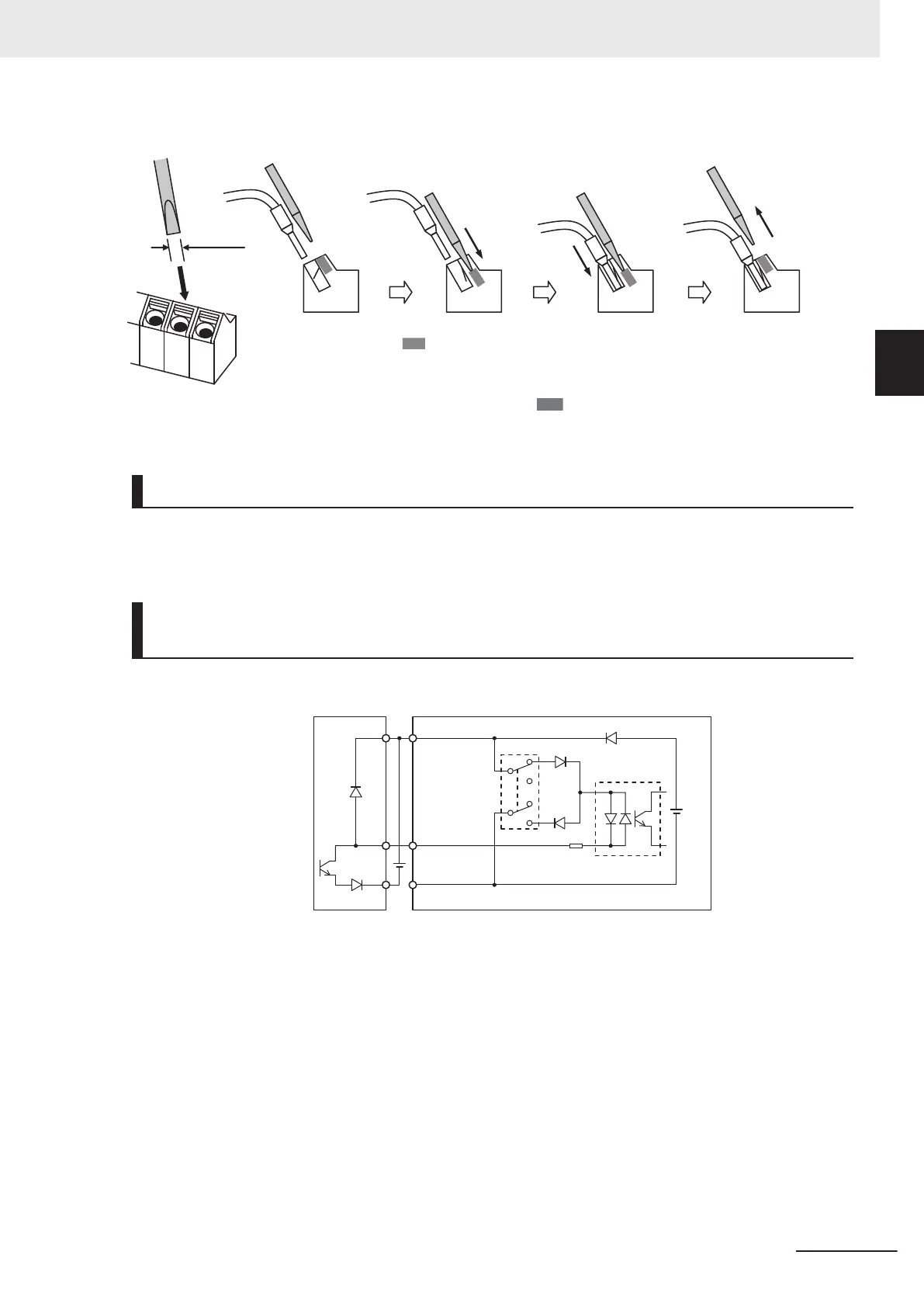
3 Remove the flat-blade screwdriver to clamp the wire.
2.5mm
Insert the wire.
Remove the
flat-blade screwdriver
to clamp the wire.
Push in the shaded
portion with a
flat-blade screwdriver.
Note
To disconnect, pull out the wire with the shaded ( ) portion pushed in with a flat-blade screwdriv-
er.
Selecting Input Control Logic
By factory default, the multifunction input terminals are set to sink logic (NPN).
To change the input control logic to source logic (PNP), switch SW1 to the SOURCE side.
Multifunction Input Terminals and Programmable Controller Con-
nection
Sink logic
+24
DI1 to DI7
DIC
Output unit Inverter
Photocoupler
Sink
Source
24 VDC
2 Design
2-61
M1 Series EtherCAT Type User’s Manual (I670)
2-3 Wiring
2
2-3-5 Wiring for Control Circuit Terminals
 Loading...


