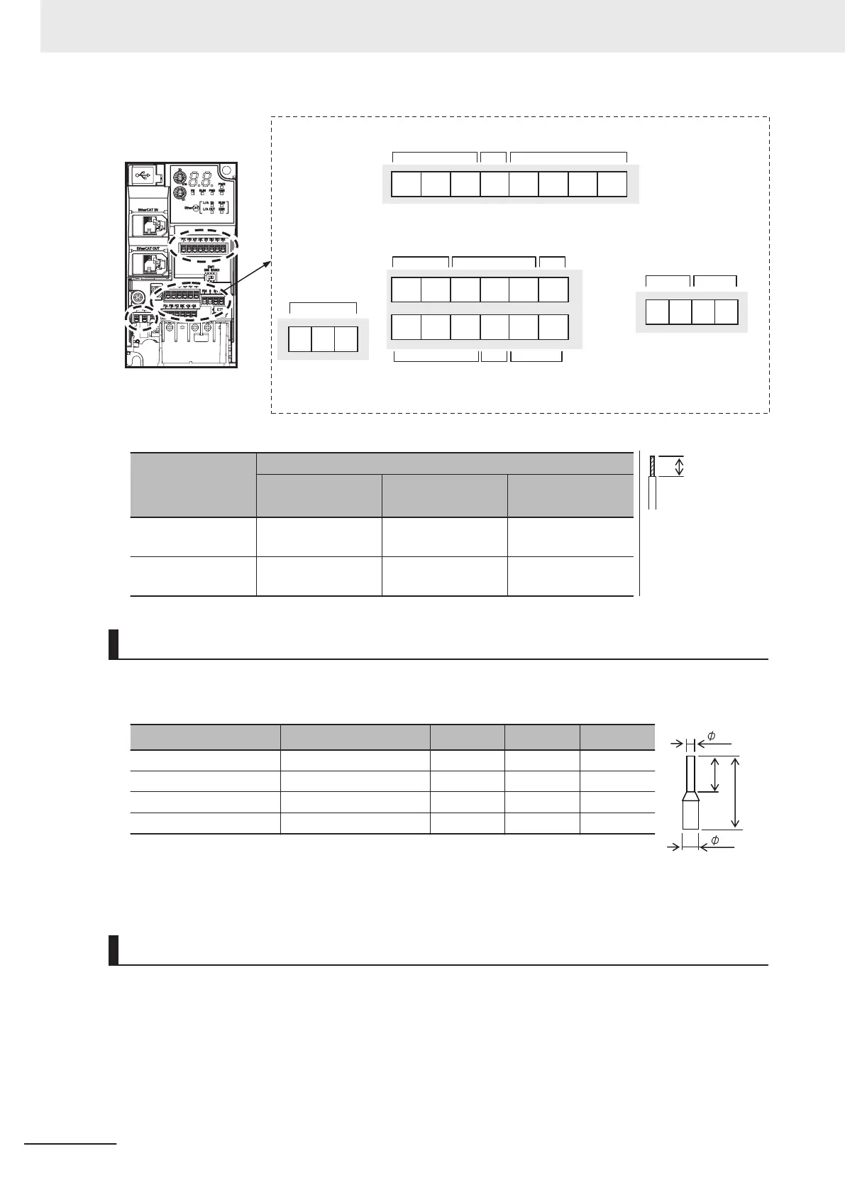
ROA ROB ROC
SF1 SF2P24 0
DI1 DI2 DI3 DI4AI1 AIC+10PTC
DI7 DICDI5 DI6DOCDO1
DIC +24 +24PIB PIZPIA
Analog input
and power supply
Relay output
Output
Power
supply
Pulse input
Input
common
and power supply
Input common
and power
supply
Input
Input
Input
common
Input
Backup power
supply
Applicable wire
Solid wire mm
2
(AWG)
Stranded wire
mm
2
(A
WG)
Ferrule mm
2
(A
WG)
Other than below
0.2 to 1.5
(AWG24 to 16)
0.2 to 1.0
(AWG24 to 17)
0.25 to 0.75
(AWG24 to 18)
ROA/ROB/ROC
SF1/SF2
0.2 to 1.5
(AWG24 to 16)
0.2 to 1.0
(AWG24 to 17)
0.25 to 0.75
(AWG24 to 18)
8mm
S
heath strip length
should be approx.
8 mm for solid/
stranded wire
Recommended Terminal
To improve ease of wiring and reliability in connection, it is recommended to use ferrules with the fol-
lowing specifications for signal wires.
Wire size mm
2
(AWG) Ferrule type
*1
L [mm] ϕd [mm] ϕD [mm]
0.25 (24) AI 0.25-8YE 12.5 0.8 2.0
0.34 (22) AI 0.34-8TQ 12.5 0.8 2.0
0.5 (20) AI 0.5-8WH 14 1.1 2.5
0.75 (18) AI 0.75-8GY 14 1.3 2.8
*1.
Manufacturer: PHOENIX CONTACT
Crimping tool: CRIMPFOX 6
Wiring Method
1 Push in the orange colored portion of the control circuit terminal block with a flat-blade screw-
driver (blade width: 2.5 mm max.) to open the wire insertion hole.
2 With the flat-blade screwdriver pushed in, insert the wire or ferrule into the wire insertion
(round) hole.
2 Design
2-60
M1 Series EtherCAT Type User’s Manual (I670)
 Loading...


