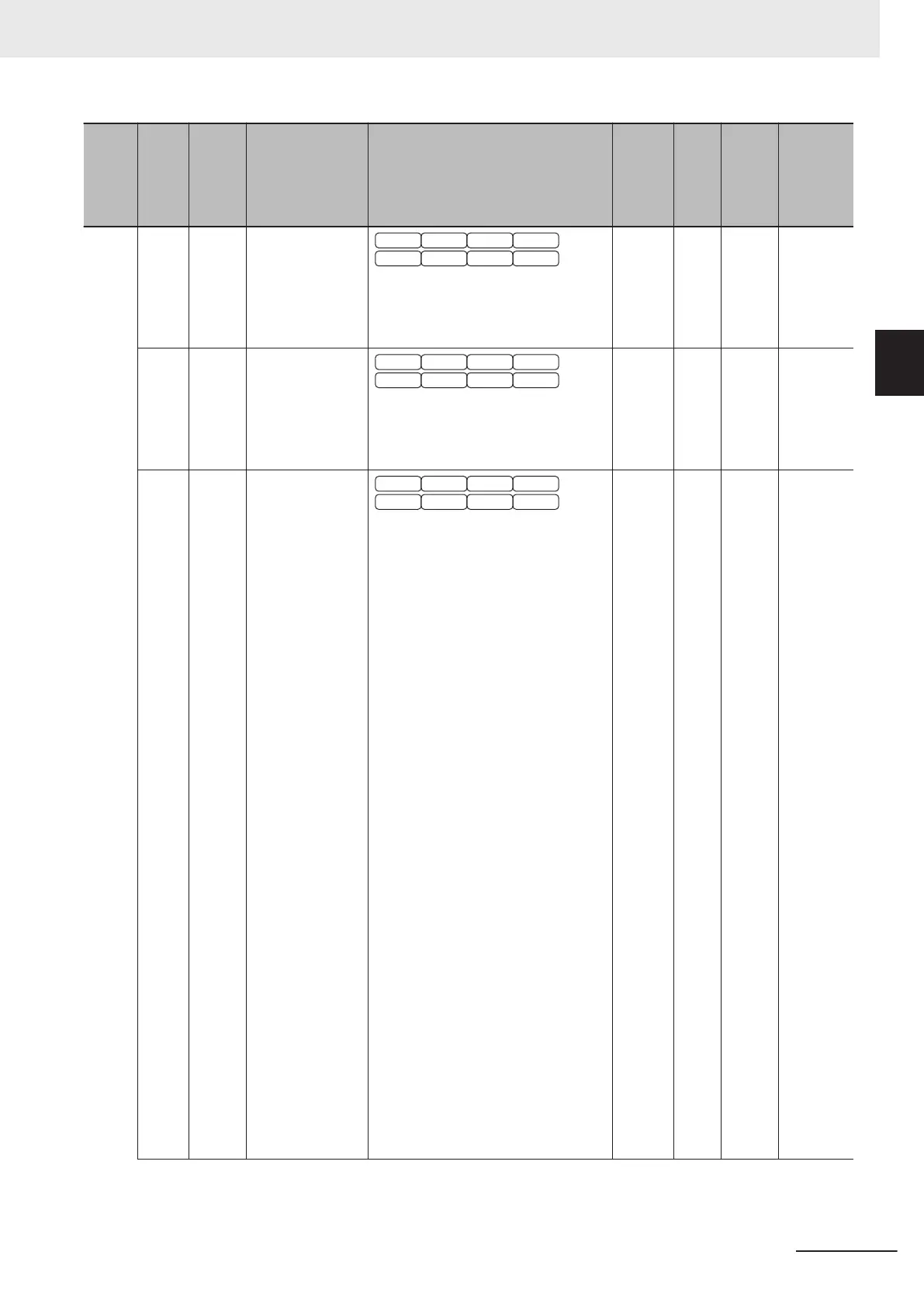
Index
(hex)
Sub-
index
(hex)
Pa-
rame-
ter No.
Function name Monitor or data range
Default
data
Set-
ting
dur-
ing
RUN
Unit
PDO
map
24 H435 Touch Probe 1
Source
V/f DTV
PG V/f PG DTV
SLV PGV
PM SLV PM PGV
1: External Latch Input 1 (EXT1)
2: External Latch Input 2 (EXT2)
6: Phase Z
1 --- --- Possible
25 H436 Touch Probe 2
Source
V/f DTV
PG V/f PG DTV
SLV PGV
PM SLV PM PGV
1: External Latch Input 1 (EXT1)
2: External Latch Input 2 (EXT2)
6: Phase Z
2 --- --- Possible
26 H437 Touch Probe
Function
V/f DTV
PG V/f PG DTV
SLV PGV
PM SLV PM PGV
0000 to FFFF hex
Bit 15 to 13: Fixed to 0
Bit 12: Latch operation 2
0: Disable
1: Enable
Bit 11 to 10: Latch trigger 2
00: External Latch Input 2 (EXT2)
01: Phase Z
10: Depends on setting of H436
1
1: Disable
Bit 9: Latch mode 2
0: Trigger First Event Mode
1: Continuous Mode
Bit 8: Latch function 2
0: Disable
1: Enable
Bit 7 to 5: Fixed to 0
Bit 4: Latch operation 1
0: Disable
1: Enable
Bit 3 to 2: Latch trigger 1
00: External Latch Input 1 (EXT1)
01: Phase Z
10: Depends on setting of H435
11: Disable
Bit 1: Latch mode 1
0: Trigger First Event Mode
1: Continuous Mode
Bit 0: Latch function 1
0: Disable
1: Enable
0
√
--- Possible
Appendices
A-145
M1 Series EtherCAT Type User’s Manual (I670)
A-4 Lists of Manufacturer Specific Objects 2
(Inverter Parameters)
A
A-4-9 H Group Parameter List (High Level Functions)
 Loading...


