Home
Omron
UPS
BU100RS
Page 23
Omron BU100RS - Page 23
102 pages
Manual
Save Page as PDF
To Next Page
To Next Page
To Previous Page
To Previous Page
Loading...
2
Inst
allati
on and conn
ection
2-1
Insta
llation
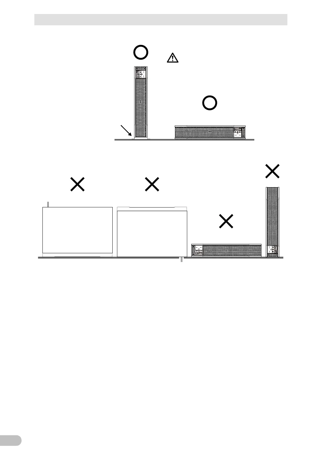
BU1
00
RS
22
<B
U
100R
S>
(Air vent
s are facing upward)
Ba careful not
to get your fingers
caught when arranging t
he unit.
Correct Posi
tions
Note
:
F
or vertical installation,
be
sure to use opt
ional
vert
i
-
cal floor mount
ing brackets
(BAP100R).
Incorrec
t Positions
22
24
Table of Contents
Main Page
Default Chapter
2
Introduction
2
Procedure from Installation to Operation
4
Table of Contents
5
Safety Precautions
8
1 Preparation
17
Unpacking the Product
17
Checking the Contents
17
Related Products
18
Name of each Part
19
Diagram of the Input/Output Circuit Block
21
2 Installation and Connection
22
Installation
22
Mounting the UPS to the Rack (Communication/Hub Rack - EIA 19" Rack)
24
Stationary Installation
31
Connecting the Equipment
32
Connecting a Device to the Power Supply Output
32
Connecting a Device to a Terminal Block
34
Connecting the AC Input
37
3 Check and Start Operation
38
The Name and Function for the Operation and Display
38
Name of each Part
38
The Meaning of each LED
38
Switch
39
Setting Switch
39
Beep Sound
44
Checking the Operation
45
Start and Stop Procedures and Basic Operation
48
Start and Stop Procedures
48
Interpreting Beeps and Displays
50
Displays and Beeps in Normal Operations
50
Displays and Beeps While Testing
51
Displays and Beeps During Power Failure or AC Input Error
51
Displays and Beeps When There Is an Equipment Failure
52
Display and Beep for Battery Replacement
55
UPS Operation Mode Settings
56
Settable Items and Explanations
56
Settings
58
4 Maintenance and Inspection
62
Checking the Battery
62
Battery Life Expectancy
62
Self-Diagnosis Test
62
Estimated Backup Time
63
Replacing the Battery
65
Notification that the Battery Needs to be Replaced
66
Procedure for Replacing the Battery
67
Replacing the Fan
72
Fan Replacement Procedure
73
Cleaning
75
Inspection of Rack Mounted Condition
75
5 To Perform Shutdown Processing of the Devices When a Power Failure Occurs
76
The Outline on the UPS Monitoring Software
76
UPS Monitoring Software Function List
76
The Supported os of the UPS Monitoring Software
78
When Using the UPS Monitoring Software
78
What Is the Poweract Pro
78
What Is the Simple Shutdown Software
79
How to Connect
79
6 Using the Contact Signal Functions
81
Contact Signal Functions
81
Type of Output Signals
81
Type of Input Signals
81
Contact Signal Port (Female D-SUB 9 Pin)
82
Remote ON/OFF Port
82
Contact Signal Ratings
82
Contact Signal Circuit
82
Example of the Use of the Contact Signal Circuit
83
Precautions and Notes for the Use of the Contact Signal
83
7 Troubleshooting
84
8 Note of Chinese
85
9 References
94
Specifications
94
Dimensions
95
Battery Life
99
China Rohs Information
100
Related product manuals
Omron BU1002SW
116 pages
Omron Powli BU1002SW
94 pages
Omron BU5002R
135 pages
Omron Powli BU75RW
99 pages
Omron Powli BU50SW
74 pages
Omron BN50T
110 pages
Omron BN75R
85 pages
Omron Powli BY35S
63 pages
Omron POWLI BX35F
59 pages
Omron POWLI BN50S
99 pages
Omron POWLI BY50FW
69 pages
Omron POWLI BY75SW
69 pages