3 Check and start operation
3-1 The name and function for the operation and display
BU100RS
3 Check and start operation
3-1 The name and function for the operation and display
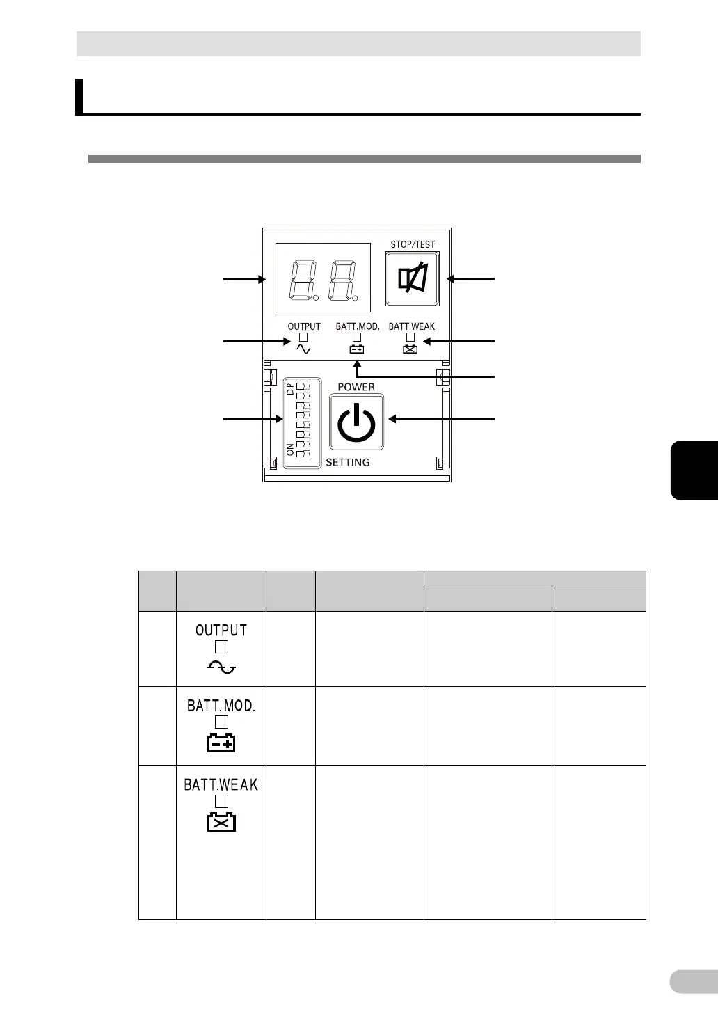
3-1-1 Name of each part
A
B
E
G
D
C
F
A: Status indicator
B: “Power supply output” LED
C: “Battery mode” LED
D: “Battery replacement” LED
E: “Setting switch”
F: “Power” switch
G: “Buzzer Pause/Test” switch
<Enlarged view of the operation panel>
3-1-2 The meaning of each LED
Sign of
the
figure
LED Color Name Status
Lit. Not lit.
LED
is ON.
output is OFF.
C
Orange “Battery mode” LED Backup is operating. This
status is called “Battery
Mode”.
operating.
LED
If battery replacement is
required due to battery
performance degradation
(including deterioration); if
the battery voltage
significantly drops and
becomes the specified
value or lower; if the
battery is not connected;
or if the battery voltage is
replacement is not
necessary.