2 Installation and connection
2-2 Connecting the equipment
BU100RS
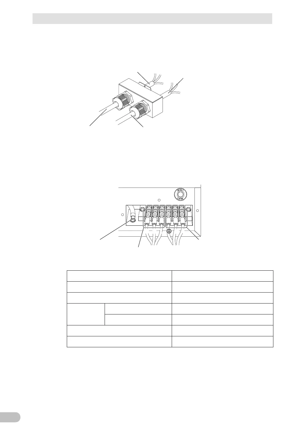
2. Run the wires through the terminal block cover (with cable clamp) after removing the
cap of cable clamp for AC output side.
AC inputAC output
Already connected to
AC input terminal block
Output
3. Connect the L line to L. Connect the N line to N, and connect the G line to G.
Connections to the terminal block shall comply with the standards in Table 1.
GNL GNL
Input terminal
(mounted by default)
(Input surge protection GND)
Output terminal
Table 1
Connectable wire size (copper wire only)
Outer diameter of the calbe
Recommended ring terminal for the wire