63
Wiring Methods Section 2-4
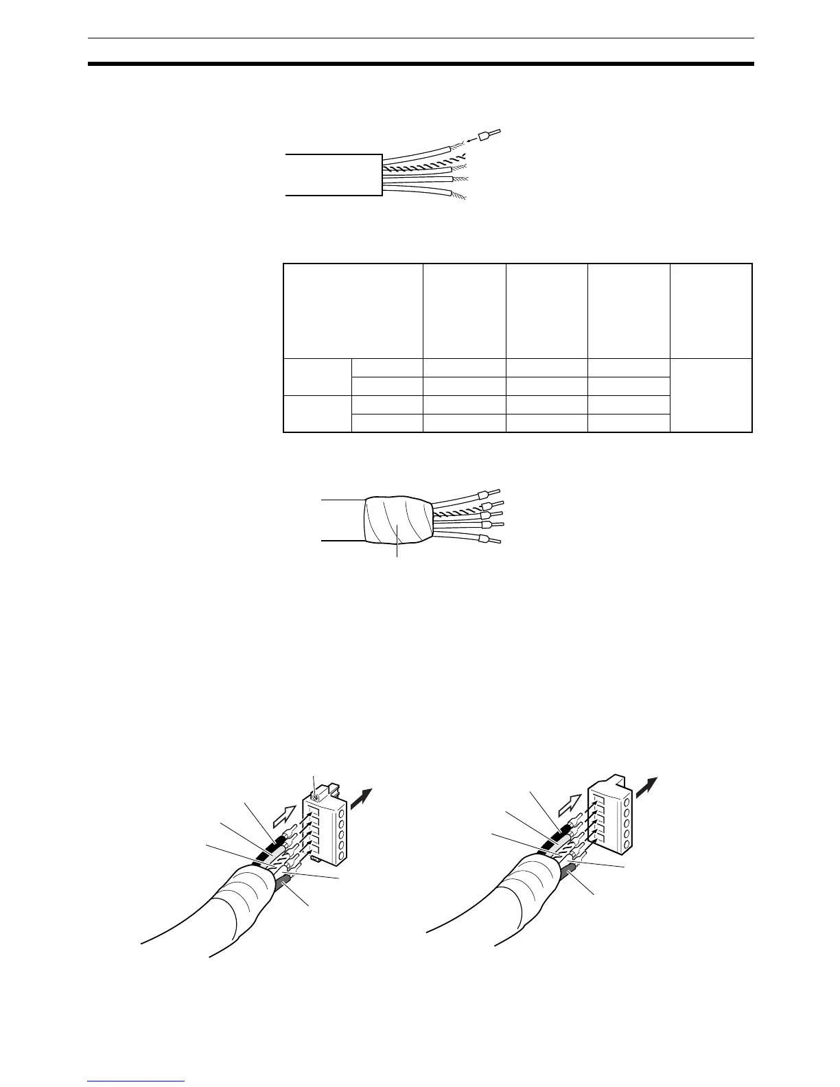
4. Attach the crimp terminals (solderless pin terminals) to the lines and use
the proper Crimping Tool to crimp the terminal securely.
Note We recommend using the following crimp terminals and crimping tools.
• PHOENIX CONTACT, AI-series Crimp Terminals
5. Cover the end of the cable with electrical tape or heat-shrink tubing as
shown in the following diagram.
6. Check that the connector is oriented correctly and the wire set screws are
loose enough to insert the wires. Insert the power lines, signal lines, and
shield wire in the correct holes in the following order (top to bottom): black,
blue, shield, white, and red.
• Straight Connectors
With straight connectors, the wiring direction and connector insertion
direction are the same. Use the straight connectors if there is sufficient
wiring space.
• Right-angle Connectors
With right-angle connectors, the wiring direction and connector inser-
Crimp terminal
Cable type XW4B-05C1-
H1-D
XW4B-05C1-
V1R-D
MSTB2.5/5-
ST-5.08AU
XW4B-05C4-
TF-D
XW4B-05C4-
T-D
XW4G-
05C1-H1-D
XW4G-
05C4-TF-D
Crimping
Tool
Using thin
cables
Signal lines AI0.25-6YE AI0.25-8YE AI0.25-8YE CRIMPFOX
ZA3
Power lines AI0.5-6WH AI0.5-10WH AI0.5-10WH
Using thick
cables
Signal lines A1-6 A1-10 A1-10
Power lines AI 2.5-8BU AI 2.5-10BU AI 2.5-10BU
Electrical tape or
heat-shrink tubing
Straight Connector with Attachment Screws
Black (V
−)
Blue (CAN L)
Shield
White (CAN H)
Red (V+)
Black (V
−)
Blue (CAN L)
Shield
White (CAN H)
Red (V+)
Straight Connector without Attachment Screws
Wiring
direction
Wiring
direction
Insertion
direction
Insertion
direction
Attachment
screw