64
Wiring Methods Section 2-4
tion direction are perpendicular. Use right-angle connectors if there is
insufficient wiring space in front of the DeviceNet connectors and the
connectors must be wired from the side.
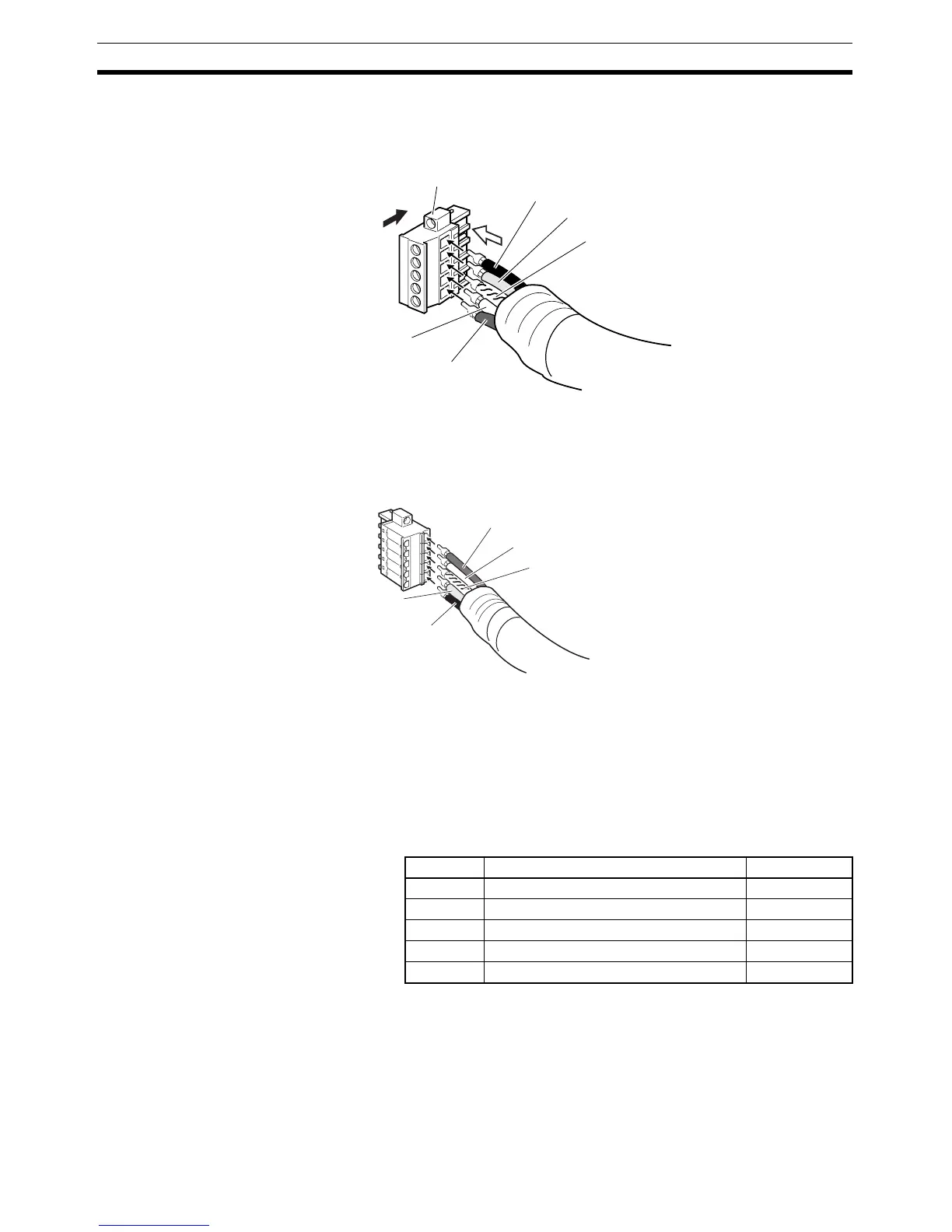
Connectors without set screws do not require lines to be secured with
screws as with previous connectors. Push up the orange lever and
then insert each line into the back of each hole.
Release the orange lever after inserting the lines, and gently pull each
line to check that it is securely connected to the connector.
Note (a) Be sure that the wire set screws are sufficiently loosened before
attempting to insert the lines. If these screws are not loose, the
wires will go into the space in the back of the connector and can-
not be locked with the set screws.
(b) There are colored stickers provided on the Master Unit and Slave
Units that match the colors of the lines to be inserted. Be sure that
the colors match when wiring the connectors.
(c) The following table shows the cable colors:
7. Tighten the connector’s set screws on the wires using a slotted screwdriver
that doesn’t taper at the tip, which will prevent the screwdriver from binding
in the connector. Tighten the screws to a torque of between 0.25 and
0.3 N
⋅m
Color Signal Symbol
Black Communications power supply, negative V−
Blue Signal line, Low CAN L
--- Shield S
White Signal line, High CAN H
Red Communications power supply, positive V+
Insertion
direction
White (CAN H)
Red (V+)
Black (V
−)
Blue (CAN L)
Shield
Wiring
direction
Attachment
screw
Black (V−)
Red (V+)
Blue (CAN L)
White (CAN H)
Shield