3 - 19
3 Part Names and Basic Procedures
E5@C Digital Temperature Controllers User’s Manual (H174)
3-4 Procedures after Turning ON the Power Supply
3
3-4-2 Basic Procedure
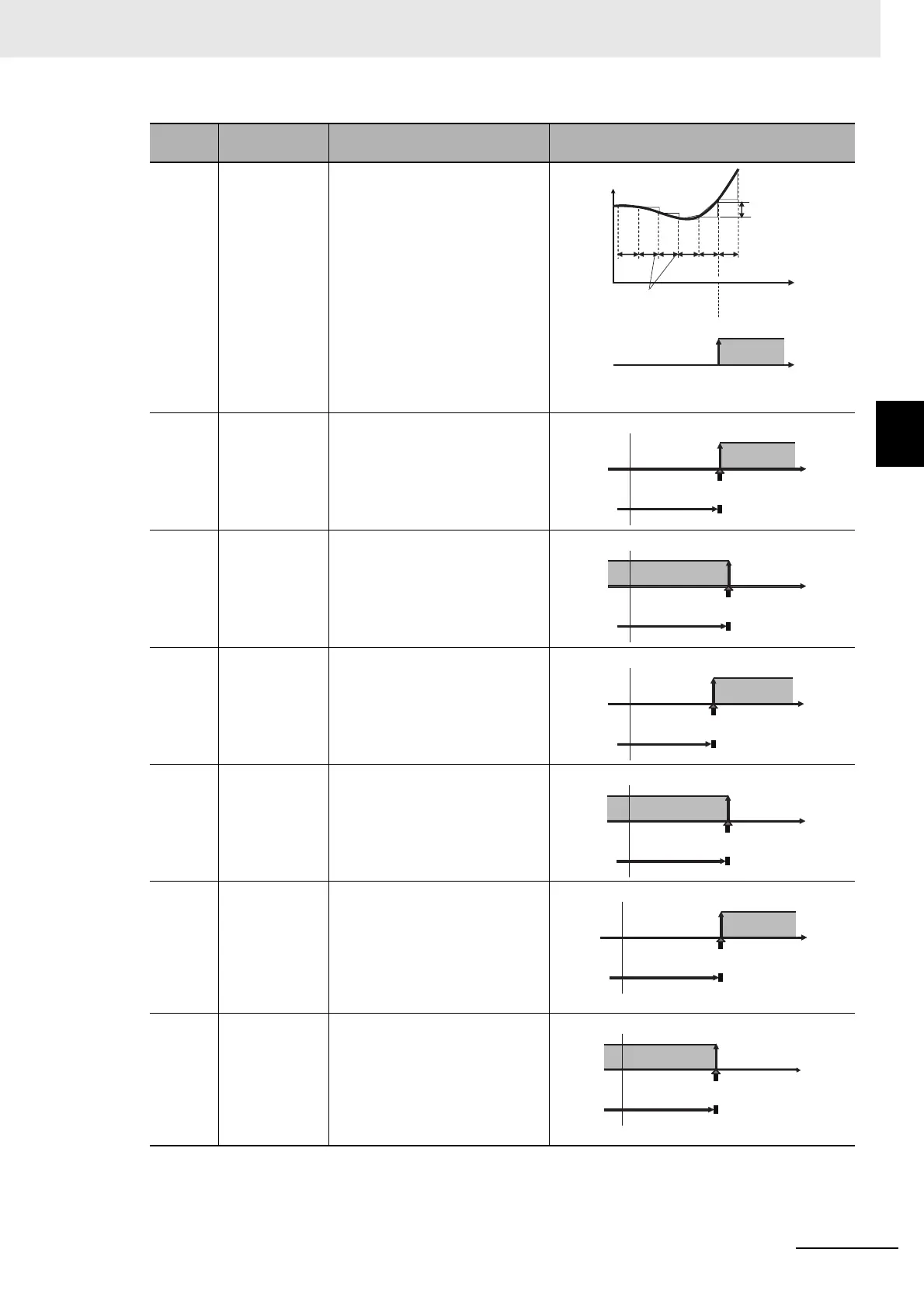
13 PV change rate
alarm
The alarm output turns ON if the
change in the PV within the
specified calculation period
exceeds a specific width.
The PV rate of change calculation period and
the alarm value are set in parameters.
14 SP
absolute-value
upper-limit
alarm
The alarm output is ON while the
SP is equal to or higher than the
alarm value.
15 SP
absolute-value
lower-limit
alarm
The alarm output is ON while the
SP is equal to or lower than the
alarm value.
16 MV
absolute-value
upper-limit
alarm
The alarm output is ON while the
MV is equal to or higher than the
alarm value.
17 MV
absolute-value
lower-limit
alarm
The alarm output is ON while the
MV is equal to or lower than the
alarm value.
18 RSP
absolute-value
upper-limit
alarm (Valid
only with a
remote SP
input.)
The alarm output is ON while the
RSP is equal to or higher than the
alarm value.
19 RSP
absolute-value
lower-limit
alarm (Valid
only with a
remote SP
input.)
The alarm output is ON while the
RSP is equal to or lower than the
alarm value.
Set
value
Alarm type Description Operation
PV
PV Change Rate Alarm Output
PV rate of change calculation period
Change rate width
ON
OFF Time
Time
ON
OFF
0
SP
Upper-limit alarm
point (e.g., 100°C)
Alarm value (e.g., 100°C)
Example:
ON
OFF
0
SP
Lower-limit alarm
point (e.g., 100°C)
Example:
Alarm value (e.g., 100°C)
ON
OFF
0
MV
Upper-limit alarm
point (e.g., 60%)
Alarm value (e.g., 60%)
Example for Standard Control:
ON
OFF
0
MV
Lower-limit alarm
point (e.g., 80%)
Example for Standard Control:
Alarm value (e.g., 80%)
ON
OFF
0
RSP
Upper-limit alarm
point (e.g., 100°C)
Alarm value (e.g., 100°C)
Example:
ON
OFF
0
RSP
Lower-limit alarm
point (e.g., 100°C)
Example:
Alarm value (e.g., 100°C)

 Loading...


