2 - 13
2 Preparations
E5@C Digital Temperature Controllers User’s Manual (H174)
2-1 Installation
2
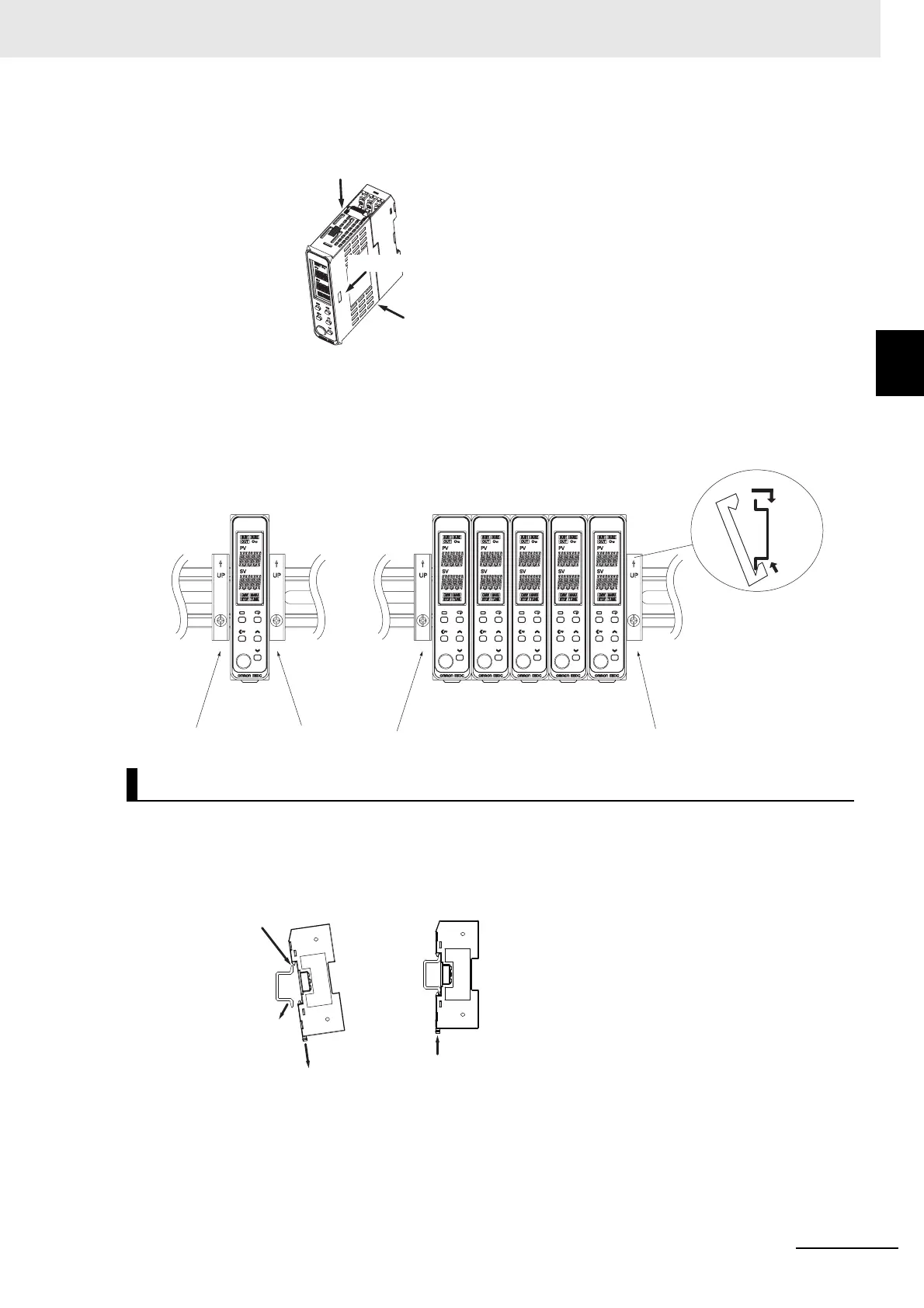
2-1-3 Mounting
Removing the Main Unit
Press in the two hooks on the Main Unit and remove the Main Unit from the Terminal Unit.
End Plate Installation
Make sure to attach PFP-M End Plates to the ends of the Units.
• End Plate (sold separately)
PFP-M
Mounting to and Removing from DIN Track
• Mounting a Unit
Mount the Main Unit after first mounting the Terminal Unit on the DIN Track.
E5DC-B
(1)
(1) Push in the hooks.
(2) Pull out the Main Unit.
Individual Mounting Group Mounting
(1)
(2)
(1) Pull down the hook.
(2) Catch the top hook
on the DIN Track.
(3) Press the Unit
onto the DIN
Track.
(4) Make sure that the
hooks are locked
in place.

 Loading...


