2 Preparations
2 - 26
E5@C Digital Temperature Controllers User’s Manual (H174)
Model Numbers
The number of auxiliary outputs on the E5CC is given in the following location in the model number.
* These cannot be selected if 5 (screw terminals with cover) is selected for the terminal type.
Terminal Details
Model Numbers
The input power supply specification of the E5CC is given in the following location in the model number.
Terminal Details
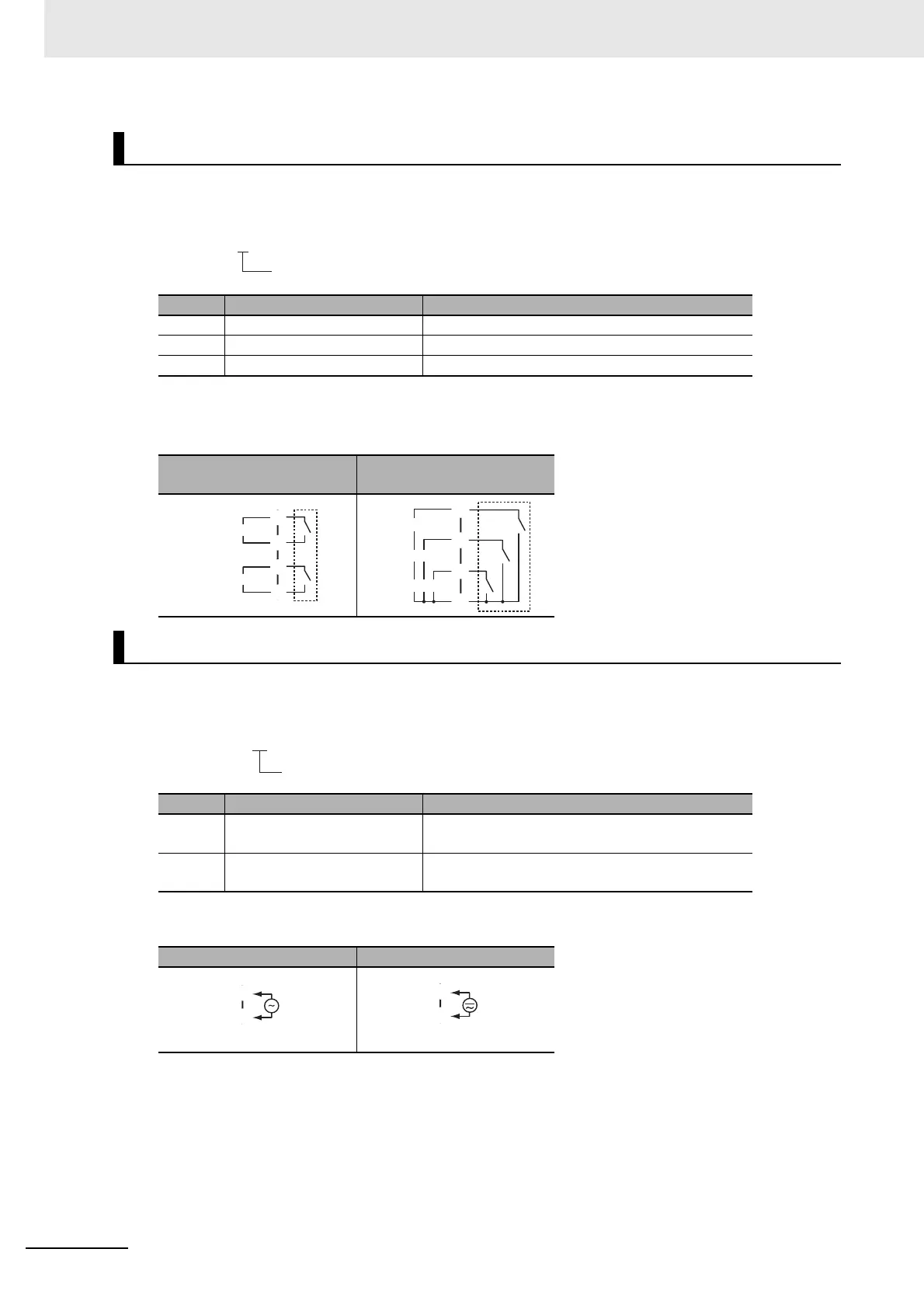
Auxiliary Outputs
Code Auxiliary outputs Specification
0* None None
2* Model with 2 auxiliary outputs SPST-NO, 250 VAC, 3 A
3 Model with 3 auxiliary outputs SPST-NO, 250 VAC, 2 A
Model with 2 auxiliary
outputs
Model with 3 auxiliary
outputs
Input Power Supply
Code Specification Power consumption
A 100 to 240 VAC, 50/60 Hz Option number 000: 5.2 VA max.
Other option numbers: 6.5 VA max.
D 24 VAC, 50/60 Hz
24 VDC (no polarity)
Option number 000: 3.1 VA max./1.6 W max.
Other option numbers: 4.1 VA max./2.3 W max.
100 to 240 VAC 24 VAC/DC
E5CC-@@ @ @ @ M-@@@
No. of auxiliary outputs
G
H
I
J
Auxiliary output 2
Auxiliary output 1
G
H
I
J
Auxiliary output 2
Auxiliary output 1
Auxiliary output 3
E5CC-@@ @ @ @ M-@@@
Input power supply
L
K

 Loading...


