Section 7 Communication (Modbus)
7-20
Communication
(Modbus)
This command is used to write setting data. The number of elements
can be set from H'0004 to 0068 (4 to 104) to allow successive writing
of 2 to 52 items of setting data in contiguous addresses.
To specify the variable type or address, see "Appendix Setting list"
(P.A-6).
Write setting data to setting area 1 from setting area 1. If written from
setting area 0, an error will result.
To use this command, "Write via communication" must be enabled
using the "Write via communication" operation command.
To store setting data of Operation and Adjustment setting levels in
non-volatile memory, select "Backup" with the "Write mode" command.
If not set to "Backup", the setting data will not remain in memory when
the power is turned off. For more information on Operation and
Adjustment levels, see "4.1 Setting levels and key operation" (P.4-2).
The above indicates a normal end. For information on error responses,
see "7.6 Writing to the variable area" (P.7-12).
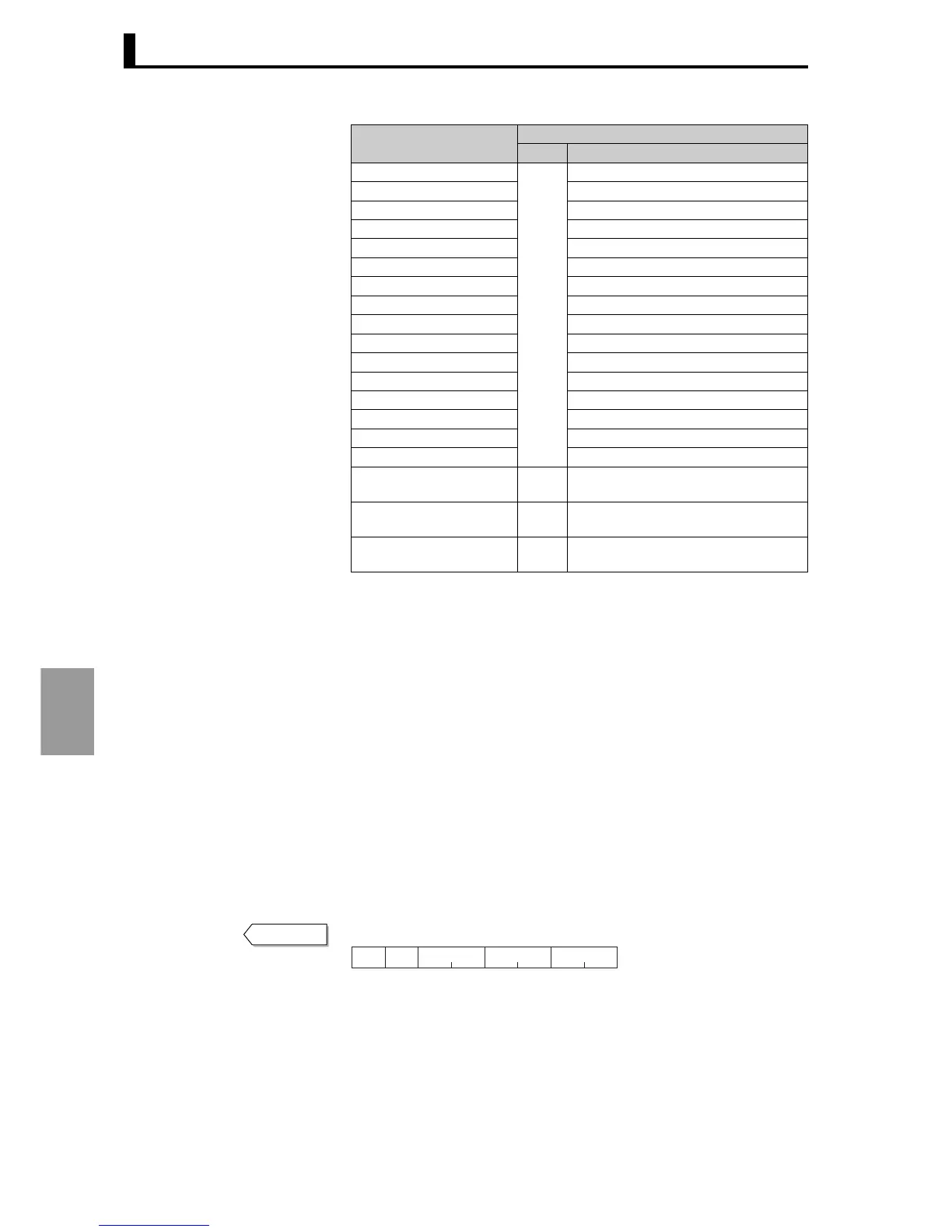
Address
Explanation
Ch
1
Setting data of setting area 0
H'0600 to 060E RUN level
H'0700 to 0744 Adjustment level
H'0800 to 0818 Adjustment level 2
H'0900 to 09DE Bank setting level
H'0A00 to 0A8E PID setting level
H'0B00 to 0B6E Approximation setting level
Setting data of setting area 1
H'0C00 to 0C20 Input initial setting level
H'0D00 to 0D26 Control initial setting level
H'0E00 to 0E60 Control initial setting 2 level
H'0F00 to 0F20 Alarm setting level
H'1000 to 100E Display adjustment level
H'1100 to 110C Communications setting level
H'1200 to 1218 Special function setting level
H'1300 to 1332 Expansion control setting level
H'4000 added to above
addresses
2 Same setting data as channel 1
H'8000 added to above
addresses
3 Same setting data as channel 1
H'C000 added to above
addresses
4 Same setting data as channel 1
Response
H’10
Slave
address
Function
mode
Write start
address
Number of
elements
CRC-16
22211
 Loading...


