9.3 Thermocouple input calibration
9-7
User calibration
7. Press the key M to obtain the display at left.
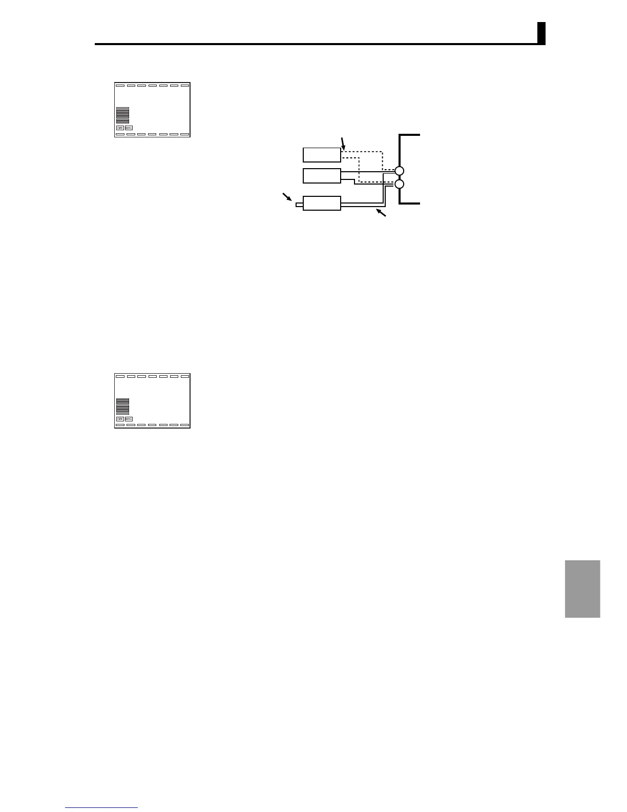
8. Change the wiring as shown below.
Disconnect the STV and enable the thermocouple in the cold junction
compensator. Make sure that the STV is disconnected at this time.
9. Wait until the count in Display 2 is sufficiently stable and then press the D
key. This tentatively saves the calibration data at this point.
10. Press the key M to obtain the display at left. Note that this display will not
appear if not all of the required data has been tentatively saved.
Press the U key. Display 2 will show "yes". Two seconds after the key is
released or when the M is pressed, the tentatively saved calibration data is
stored in non-volatile memory. If you do not wish to save the data in non-
volatile memory, press the M key instead of the U key.
• For a multi-point input type, connect as explained in step 2 and repeat
steps 5 to 10.
• If linear current output is selected, continue with the procedure explained
in "9.6 Output calibration" (P.9-12).
11. Turn off the power to quit calibration mode.
bia5.1
5f165
l.cal
Short circuit
STV
DMM
ZERO-CON
OUTPUT INPUT
Open without connecting
Compensating wire of selected thermocouple
However, for thermocouple E, R, S, W, and B,
compensating wire of thermocouple K is used.
−
+
str.i1
no
l.cal