4.10 Determining the PID constants (AT, manual settings)
4-21
Settings Required
for Basic Control
If you attempt to move to "RUN level" and show "PV/SP" while AT is
running, Display 2 will blink and indicate that AT is running.
• Only "Write via communication", "Run/Stop", "AT Execute/Cancel",
and "Auto/Manual" can be changed while AT is running. No other
settings can be changed.
• If "Run/Stop" is set to "Stop" while AT is running, AT will stop and
operation will stop. If "Run" is then selected, AT will not resume.
• If an input error occurs while AT is running, AT will stop. AT will run
again after recovery from the error.
• If AT is started during SP ramp, AT will run for the ramp SP.
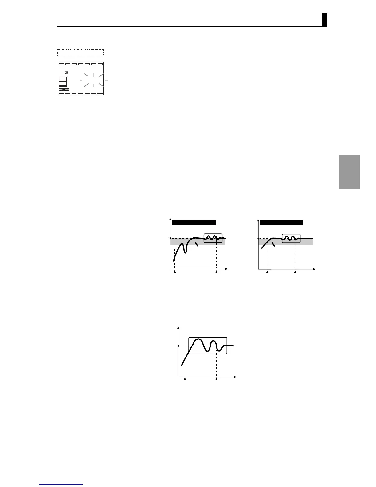
● Limit cycle The timing for generating a limit cycle varies depending on whether or
not the deviation (DV) when AT is begun is less than "the temporary
AT execution judgement deviation" (initial setting 10.0% FS).
PV during AT is as follows:
The amplitude of change of the limit cycle MV can be changed in "Limit
cycle MV amplitude".
For heating/cooling and position proportional floating type control, the
limit cycle is as follows regardless of the deviation.
AT run in progress
Present value (PV) / SP (Display 2)
25.0
1
100.0
100.0
Present
value (PV)
Present
value (PV)
Time
Time
Limit cycle MV amplitude 40% Limit cycle MV amplitude 40%
AT start
AT end
AT start
AT end
Deviation
10% FS
Deviation
10% FS
Deviation ≥ 10% FS
Deviation < 10% FS
SP SP
Present
value (PV)
Time
AT start
AT end
Limit cycle MV
amplitude 100%
SP