76
SECTION 5
Connecting a Strobe Device
F210
Setup Manual
SECTION 5
Troubleshooting and Maintenance
Connecting a Strobe Device
Use the camera’s corresponding strobe trigger output signal (STGOUT0, STGOUT1) to control the
strobe flash timing.
p.40
Check the strobe device’s specifications and set the appropriate “Shutter trigger polarity” and “Shutter
trigger width” in the Camera settings (Detail) Menu.The Camera settings (Detail) window is displayed at
startup and can be displayed at other times by selecting Camera settings from the System Menu.
Combining an OMRON Camera and Strobe
The following table shows the timing polarity.
Use a strobe that is compatible with this timing.
(*)The window used to change the shutter trigger polarity and shutter trigger pulse will not be displayed when an F150-S1A,
F160-S1 or F160-S2 Camera is connected, but the STGOUT0, STGOUT1 signals will be output with the polarity and width
shown in the table above.
Strobe specifications
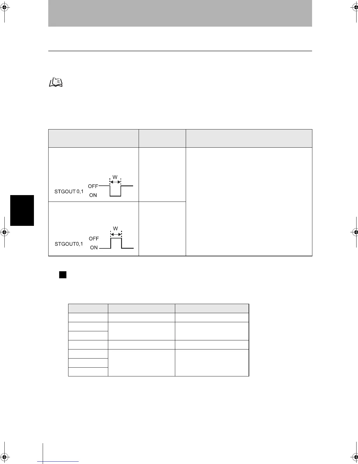
Shutter trigger
Shutter trigger polarity
Shutter trigger width
When the flash is synchronized to the
OFF-to-ON transition of the strobe trigger
signal
Positive
The “shutter trigger width” setting determines the pulse
width W.
Can be set to match the strobe’s specifications.
• When using a Double-speed Camera:
W = Shutter trigger width setting (H) 32 µs
(1H = 32 µs)
When the flash is synchronized to the
ON-to-OFF transition of the strobe trigger
signal
Negative
• When using a Camera other than a Double-speed
Camera:
W = Shutter trigger width setting (H) 63 µs
(1H = 63 µs)
Note: Depending upon the timing, W may have an error of
up to 1H.
Camera
Shutter trigger polarity
Shutter trigger width
F150-S1A Positive 3H (1H = 63 µs) (*)
F160-S1
Positive 3H (1H = 32 µs)
(*)
F160-S2
F300-S
Positive Can be set to match the strobe’s
F300-S2R
Negative 7H (1H = 63 µs)
F300-S3DR
F300-S4R
F210setUP.book76ページ2003年1月28日 火曜日 午前11時6分