20
SECTION 2
Basic System Configuration
F210
Setup Manual
SECTION 2
Installation and Connections
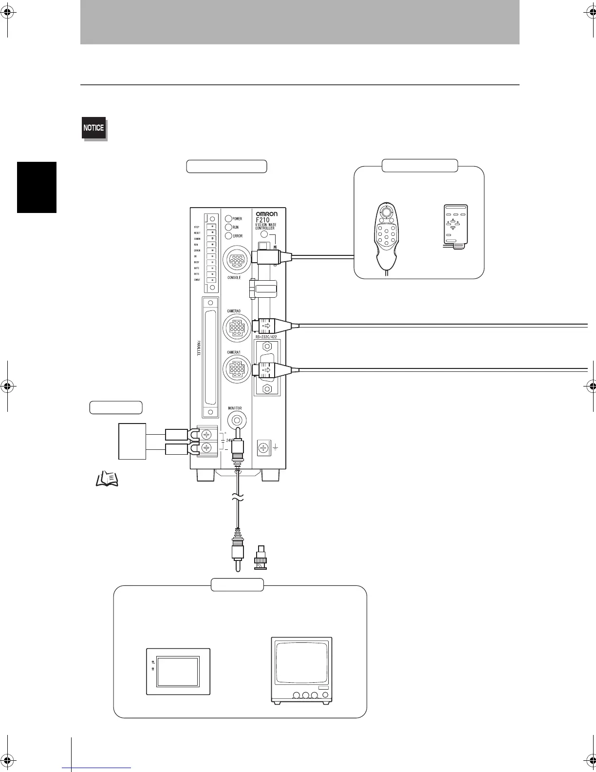
Basic System Configuration
The following diagram shows the basic system configuration.
Some of the components shown in the configuration diagram are special OMRON products that cannot be substituted with
comparable devices. Using devices other than OMRON products may result in damage to the system. (“*” indicates a special
OMRON product.)
*
*
p.30
Color LCD Monitor
F150-M05L
Monochrome CRT Video Monitor
CRT type
F150-M09
Monitor
Console
Controller
Use the Monitor to check images and
display the condition-setting menus.
BNC Jack Adapter
Included with the F150-VM Monitor Cable.
(RCA plug input)
(BNC input)
Monitor Cable
F150-VM (2 m).
The Controller performs the image processing
specified by the user settings and outputs the
measurement results.
F160-KP
(2 m cable)
F150-KP
(2 m cable)
Power Supply
Camera Cable
F150-VS (3 m)
Recommended Model
OMRON Corporation
S82K-05024
F210setUP.book20ページ2003年1月28日 火曜日 午前11時6分