43
F210
Setup Manual
SECTION 4
Connecting External Devices
SECTION 4
Connecting through the Serial Interface
Connecting through the Serial Interface
The Controller’s serial interface (RS-232C/RS-422 connector or Ethernet connector) can be used to
input signals such as measurement triggers or output signals such as measurement results.Additionally,
data that has been set in the Controller can be backed up in a personal computer.The connection method
is explained here.
For the communication parameter setting method and I/O format, refer to the Operation Manual.
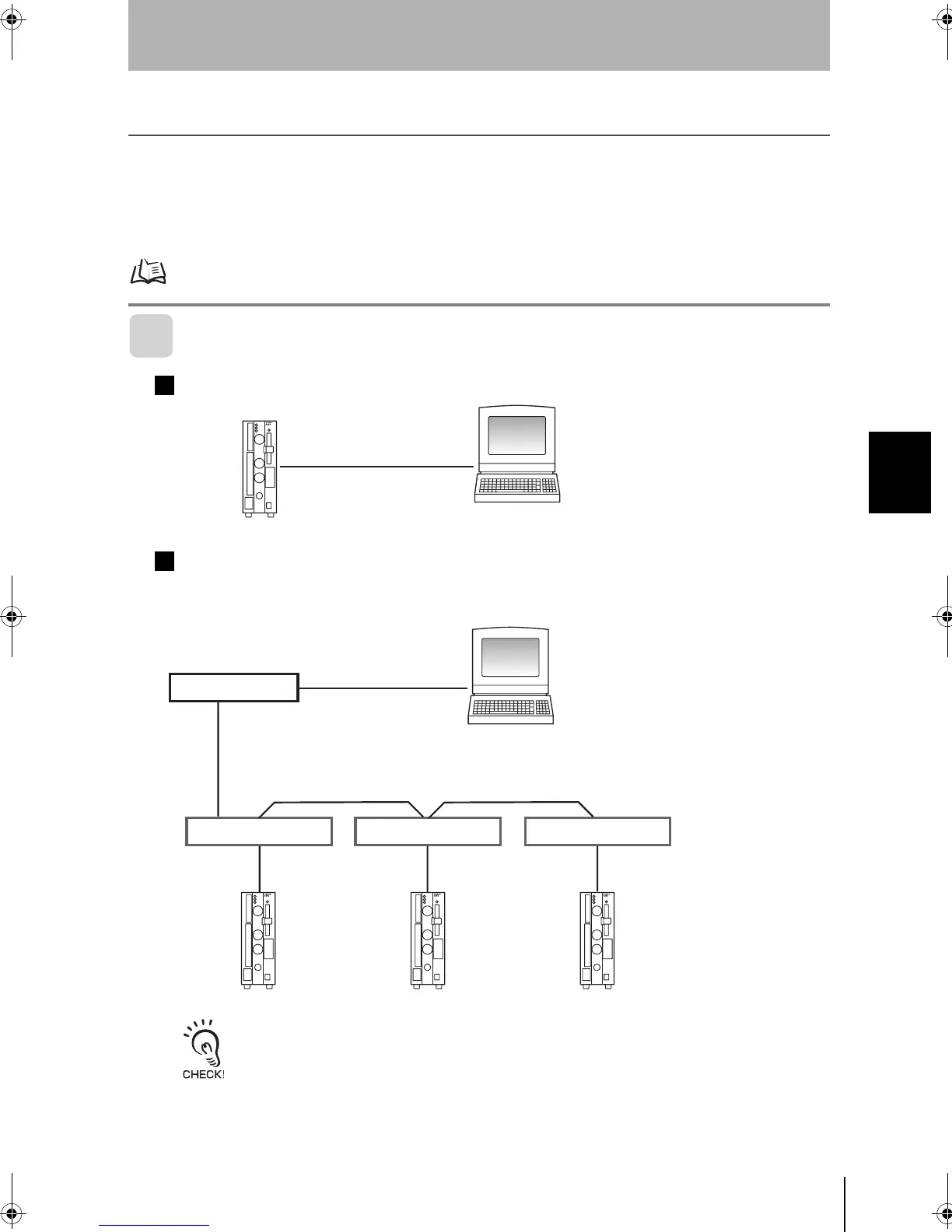
ConnectionExample
1:1 Connection (Normal, Menu Operation)
Multi-drop Connection (Normal)
Communications between one computer and several Controllers (at most 31 Controllers) is
possible using Link Adapters.
When 3G2A9-AL004-E Link Adapters are being used, termination must be set to ON in the last node in the line
and the node must be terminated as follows:
Connect 220 Ω (1/2 W min.) between RDA(-) and RDB(+).
Connect 220 Ω (1/2 W min.) between SDA(-) and SDB(+).
PC
RS-232C cable
Controller
PC
RS-232C cable
Controller Controller Controller
Recommended
Model
OMRON Corporation
B500-AL001
RS-422 cable
Recommended Model
OMRON Corporation
3G2A9-AL004-E
RS-422 cable
RS-422
cable
Link Adapter
Link Adapter
Link Adapter Link Adapter
F210setUP.book43ページ2003年1月28日 火曜日 午前11時6分