42
SECTION 4
Parallel Connection Methods
F210
Setup Manual
SECTION 4
Connecting External Devices
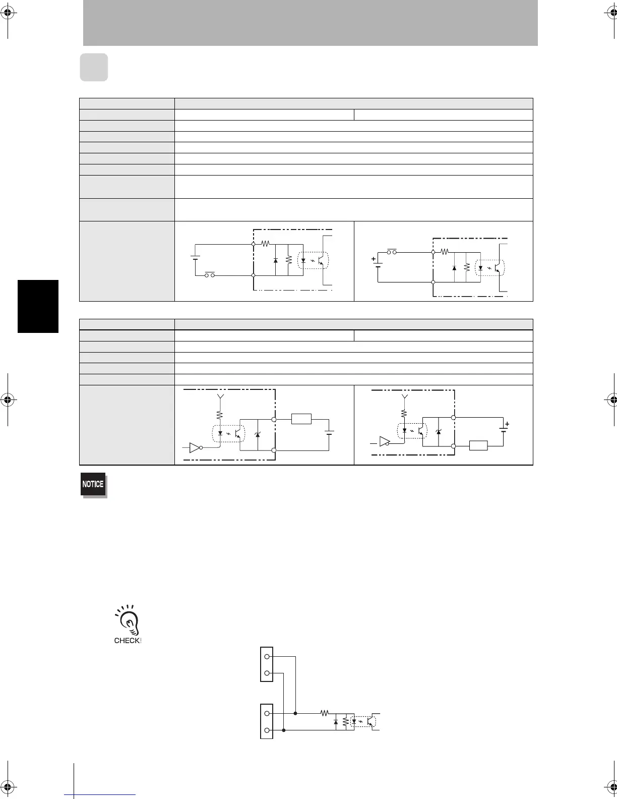
I/O Specifications
Input Specifications
Output Specifications
Do not exceed the maximum load current specified for the Controller.
*1: ON Current/ON Voltage
This refers to the current or voltage values needed to shift from the OFF¨ON state.
The ON voltage value is the potential difference between each of the input terminals and COM IN.
*2: OFF Current/OFF Voltage
This refers to the current or voltage values needed to shift from the ON¨OFF state.
The OFF voltage value is the potential difference between each of the input terminals and COM IN.
The same signals are shared by the I/O terminals and the I/O connector.
Example: STEP signal
Item Specification
Model F210-C10 (NPN mode) F210-C15 (PNP mode)
Input voltage 12 to 24 VDC ±10%
ON current *1 5 to 15 mA
ON voltage *1 8.8 V max.
OFF current *2 0.1 mA max.
OFF voltage *2 4.5 V min.
ON delay
RESET input: 10 ms max.
Other inputs: 0.5 ms max
OFF delay
RESET input: 15 ms max.
Other inputs: 0.7 ms max.
Internal circuits
Item Specification
Model F210-C10 (NPN mode) F210-C15 (PNP mode)
Output voltage 12 to 24 VDC ±10%
Load current 45 mA max.
ON residual voltage 2 V max.
OFF leakage current 0.1 mA max.
Internal circuits
COM IN
+
Input
terminal
COM IN
Input
terminal
COM OUT
Output terminal
+
Load
COM OUT
Output terminal
Load
COMIN
STEP
COMIN
STEP
I/O terminal
I/O connector
F210setUP.book42ページ2003年1月28日 火曜日 午前11時6分