22
SECTION 2
Component Names and Functions
F210
Setup Manual
SECTION 2
Installation and Connections
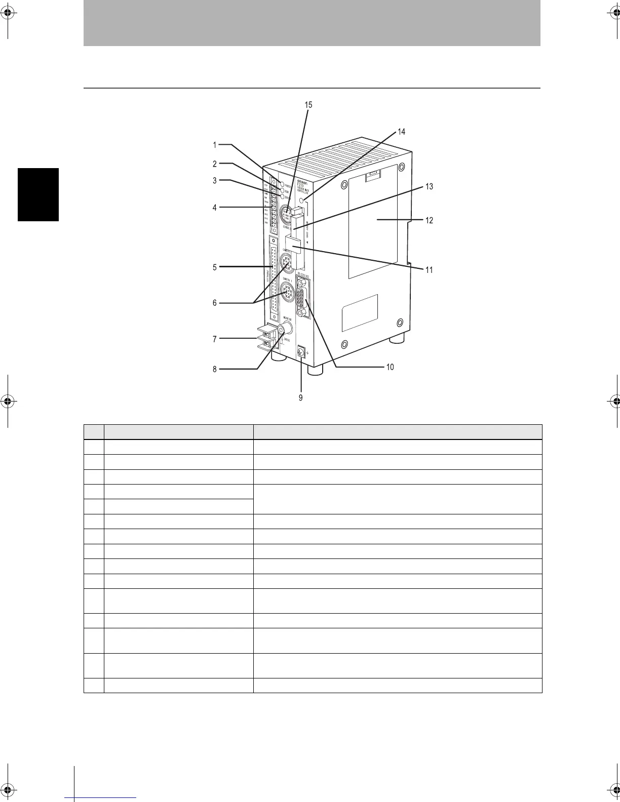
Component Names and Functions
Pin Name Function
1 POWER Indicator Lit while power is ON.
2 RUN Indicator Lit while the Controller is in Run Mode.
3 ERROR Indicator Lit when an error has occurred.
4 I/O terminals (control lines) Connect the Controller to external devices such as a sync sensor or PLC.
5 I/O terminals (control lines, data lines)
6 Camera connecting connector Connect to the Cameras.
7 Power Supply Terminals Connect to the DC power supply.
8 Monitor Connector Connects to a monitor.
9 Ground Terminal Connects to the ground wire.
10 RS-232C/RS-422 Connector Connects the Controller to an external device such as a personal computer or PLC.
11 Card lock Provided to hold the memory card to prevent it from becoming disconnected when
exposed to vibration.
12 Battery cover The battery is installed behind this cover.
13 Memory card slot Memory Cards such as the Application Software Memory Card can be inserted in
these slots.
14 Memory card indicator Lit when power is being supplied to the corresponding Memory Card. (The Memory
Card must not be inserted or removed when this indicator is lit.)
15 Console Connector Connects the Controller to a Console.
F210setUP.book22ページ2003年1月28日 火曜日 午前11時6分